HP Tx2635us HP Pavilion tx2500 Entertainment PC - Maintenance and Service Guid - Page 67
Power switch assembly, Remove the Phillips PM2.0×3.0 screw
 |
UPC - 884420449898
View all HP Tx2635us manuals
Add to My Manuals
Save this manual to your list of manuals |
Page 67 highlights
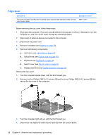
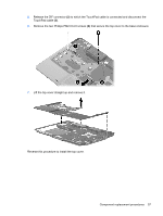
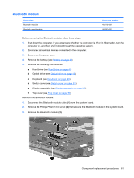
Power switch assembly Description Power switch assembly (includes power switch board cable and actuator switch) Spare part number 441142-001 Before removing the power switch assembly, follow these steps: 1. Shut down the computer. If you are unsure whether the computer is off or in Hibernation, turn the computer on, and then shut it down through the operating system. 2. Disconnect all external devices connected to the computer. 3. Disconnect the power cord. 4. Remove the battery (see Battery on page 39). 5. Remove the following components: a. Hard drive (see Hard drive on page 41) b. Optical drive (see Optical drive on page 43) c. Keyboard (see Keyboard on page 49) d. Switch cover (see Switch cover on page 51) e. Display assembly (see Display assembly on page 53) f. Top cover (see Top cover on page 56) Remove the power switch assembly: 1. Remove the two Phillips PM2.0×4.0 screws (1) that secure the power switch board to the base enclosure. 2. Remove the Phillips PM2.0×3.0 screw (2) that secures the display release hook assembly to the base enclosure. Component replacement procedures 59
-
 1
1 -
2
-
3
-
4
-
5
-
6
-
7
-
8
-
9
-
10
-
11
-
12
-
13
-
14
-
15
-
16
-
17
-
18
-
19
-
20
-
21
-
22
-
23
-
24
-
25
-
26
-
27
-
28
-
29
-
30
-
31
-
32
-
33
-
34
-
35
-
36
-
37
-
38
-
39
-
40
-
41
-
42
-
43
-
44
-
45
-
46
-
47
-
48
-
49
-
50
-
51
-
52
-
53
-
54
-
55
-
56
-
57
-
58
-
59
-
60
-
61
-
 62
62 -
 63
63 -
 64
64 -
 65
65 -
 66
66 -
 67
67 -
 68
68 -
 69
69 -
 70
70 -
 71
71 -
 72
72 -
73
-
74
-
75
-
76
-
77
-
78
-
79
-
80
-
81
-
82
-
83
-
84
-
85
-
86
-
87
-
88
-
89
-
90
-
91
-
92
-
93
-
94
-
95
-
96
-
97
-
98
-
99
-
100
-
101
-
102
-
103
-
104
-
105
-
106
-
107
-
108
-
109
-
110
-
111
-
112
-
113
-
114
-
115
-
116
-
117
-
118
-
119
-
120
-
121
-
122
-
123
-
124
-
125
 |
 |
