HP Tx2635us HP Pavilion tx2500 Entertainment PC - Maintenance and Service Guid - Page 62
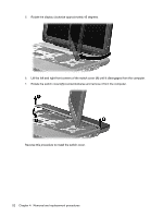
Turn the computer display-side up, with the front toward you., Open the computer.
 |
UPC - 884420449898
View all HP Tx2635us manuals
Add to My Manuals
Save this manual to your list of manuals |
Page 62 highlights
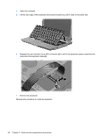
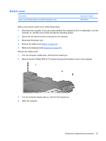
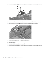
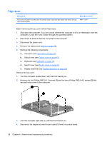
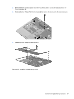
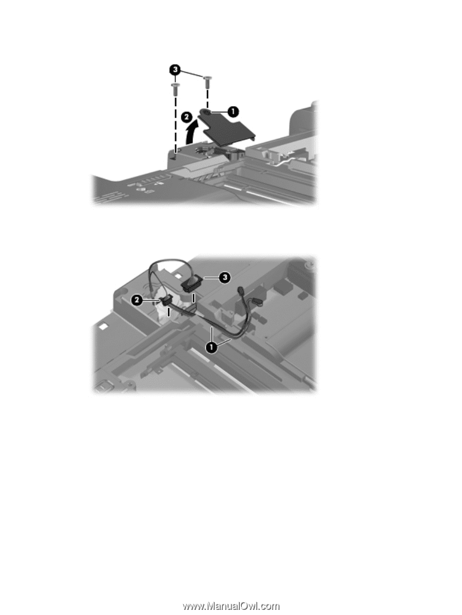
5. Remove the two Phillips PM2.5×6.0 screws (3) that secure the display assembly to the computer. 6. Remove the wireless antenna cables (1) from the routing channel built into the base enclosure. 7. Disconnect the camera cable (2) and the microphone cable (3) from the system board. 8. Turn the computer display-side up, with the front toward you. 9. Open the computer. 10. Remove the display convertible hinge cover (1). 11. Remove the two Phillips PM2.5×6.0 screws (2) that secure the display assembly to the computer. 54 Chapter 4 Removal and replacement procedures
-
 1
1 -
2
-
3
-
4
-
5
-
6
-
7
-
8
-
9
-
10
-
11
-
12
-
13
-
14
-
15
-
16
-
17
-
18
-
19
-
20
-
21
-
22
-
23
-
24
-
25
-
26
-
27
-
28
-
29
-
30
-
31
-
32
-
33
-
34
-
35
-
36
-
37
-
38
-
39
-
40
-
41
-
42
-
43
-
44
-
45
-
46
-
47
-
48
-
49
-
50
-
51
-
52
-
53
-
54
-
55
-
56
-
 57
57 -
 58
58 -
 59
59 -
 60
60 -
 61
61 -
 62
62 -
 63
63 -
 64
64 -
 65
65 -
 66
66 -
 67
67 -
68
-
69
-
70
-
71
-
72
-
73
-
74
-
75
-
76
-
77
-
78
-
79
-
80
-
81
-
82
-
83
-
84
-
85
-
86
-
87
-
88
-
89
-
90
-
91
-
92
-
93
-
94
-
95
-
96
-
97
-
98
-
99
-
100
-
101
-
102
-
103
-
104
-
105
-
106
-
107
-
108
-
109
-
110
-
111
-
112
-
113
-
114
-
115
-
116
-
117
-
118
-
119
-
120
-
121
-
122
-
123
-
124
-
125
 |
 |
5.
Remove the two Phillips PM2.5×6.0 screws
(3)
that secure the display assembly to the computer.
6.
Remove the wireless antenna cables
(1)
from the routing channel built into the base enclosure.
7.
Disconnect the camera cable
(2)
and the microphone cable
(3)
from the system board.
8.
Turn the computer display-side up, with the front toward you.
9.
Open the computer.
10.
Remove the display convertible hinge cover
(1)
.
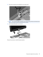
11.
Remove the two Phillips PM2.5×6.0 screws
(2)
that secure the display assembly to the computer.
54
Chapter 4
Removal and replacement procedures