HP Tx2635us HP Pavilion tx2500 Entertainment PC - Maintenance and Service Guid - Page 71
to lift the left side of the system board, Use the optical drive connector
 |
UPC - 884420449898
View all HP Tx2635us manuals
Add to My Manuals
Save this manual to your list of manuals |
Page 71 highlights
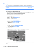
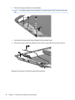
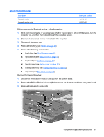
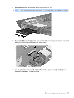
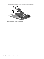
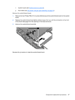
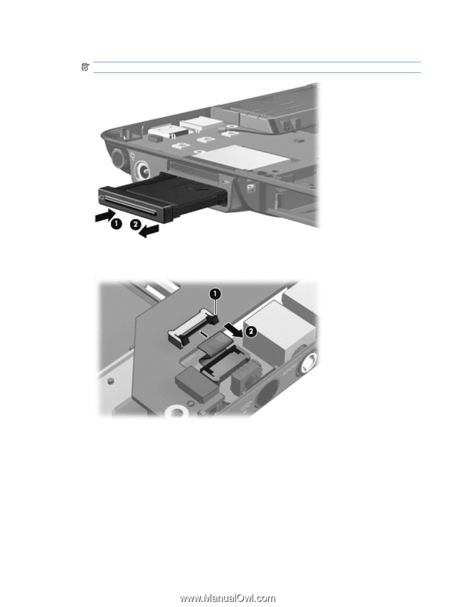
2. Remove the ExpressCard slot bezel (2) from the ExpressCard slot. NOTE: The ExpressCard slot bezel is included in the Plastics Kit, spare part number 487926-001. 3. Release the ZIF connector (1) to which the audio/infrared board cable is connected and disconnect the audio/infrared board cable (2) from the system board. 4. Use the optical drive connector (1) to lift the left side of the system board (2) until the power connector (3) is clear of the base enclosure. Component replacement procedures 63
-
 1
1 -
2
-
3
-
4
-
5
-
6
-
7
-
8
-
9
-
10
-
11
-
12
-
13
-
14
-
15
-
16
-
17
-
18
-
19
-
20
-
21
-
22
-
23
-
24
-
25
-
26
-
27
-
28
-
29
-
30
-
31
-
32
-
33
-
34
-
35
-
36
-
37
-
38
-
39
-
40
-
41
-
42
-
43
-
44
-
45
-
46
-
47
-
48
-
49
-
50
-
51
-
52
-
53
-
54
-
55
-
56
-
57
-
58
-
59
-
60
-
61
-
62
-
63
-
64
-
65
-
 66
66 -
 67
67 -
 68
68 -
 69
69 -
 70
70 -
 71
71 -
 72
72 -
 73
73 -
 74
74 -
 75
75 -
 76
76 -
77
-
78
-
79
-
80
-
81
-
82
-
83
-
84
-
85
-
86
-
87
-
88
-
89
-
90
-
91
-
92
-
93
-
94
-
95
-
96
-
97
-
98
-
99
-
100
-
101
-
102
-
103
-
104
-
105
-
106
-
107
-
108
-
109
-
110
-
111
-
112
-
113
-
114
-
115
-
116
-
117
-
118
-
119
-
120
-
121
-
122
-
123
-
124
-
125
 |
 |
2.
Remove the ExpressCard slot bezel
(2)
from the ExpressCard slot.
NOTE:
The ExpressCard slot bezel is included in the Plastics Kit, spare part number 487926-001.
3.
Release the ZIF connector
(1)
to which the audio/infrared board cable is connected and disconnect
the audio/infrared board cable
(2)
from the system board.
4.
Use the optical drive connector
(1)
to lift the left side of the system board
(2)
until the power
connector
(3)
is clear of the base enclosure.
Component replacement procedures
63