HP Visualize b2000 hp Visualize b2000 UNIX workstation service handbook (a5983 - Page 126
Replacing the I/O Fan, Removing the System Fan, Replacing the System Fan
 |
View all HP Visualize b2000 manuals
Add to My Manuals
Save this manual to your list of manuals |
Page 126 highlights
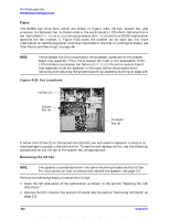
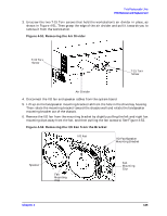
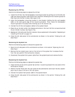
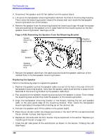
Field Replaceable Units FRU Removal and Replacement Replacing the I/O Fan Perform the following steps to replace the I/O fan: 1. Install the I/O fan into the fan/speaker mounting bracket by pulling out on the left and right fan mounting clips, inserting the fan, and then releasing the fan mounting clips so that they hold the fan in place. See Figure 4-52. 2. Align the fan/speaker mounting bracket in the chassis, holding the fan and speaker cable to the card guide edge of the mounting bracket. Then rotate the fan/speaker mounting bracket into place while holding up on the retainer tab. 3. Connect the I/O fan and speaker cables to the system board. 4. Place the air divider within the chassis and screw in the two T-15 Torx screws that hold the air divider in place. See Figure 4-51. 5. Replace all I/O cards and the PCI retainer clip as explained in the section "Replacing or Installing I/O Cards" on page 112. 6. Close the left side panel of the workstation as shown in the section "Closing the Left Side Panel." Removing the System Fan Perform the following steps to remove the system fan: 1. Open the left side panel of the workstation as shown in the section "Opening the Left Side Panel." 2. Remove the four plastic pop rivets at the corners of the system fan to release the fan from the rear panel of the workstation chassis. 3. Disconnect the system fan's power cable from the system board and remove the fan. Replacing the System Fan Perform the following steps to replace the system fan: 1. Align the flow arrow on the system fan so that it is pointing toward the rear panel of the workstation chassis. 2. Position the fan flush with the rear panel of the workstation and insert the four plastic pop rivets to secure the fan to the rear panel. 3. Connect the system fan's power cable to the system board. 4. Close the left side panel of the workstation as shown in the section "Closing the Left Side Panel." 126 Chapter 4
-
 1
1 -
2
-
3
-
4
-
5
-
6
-
7
-
8
-
9
-
10
-
11
-
12
-
13
-
14
-
15
-
16
-
17
-
18
-
19
-
20
-
21
-
22
-
23
-
24
-
25
-
26
-
27
-
28
-
29
-
30
-
31
-
32
-
33
-
34
-
35
-
36
-
37
-
38
-
39
-
40
-
41
-
42
-
43
-
44
-
45
-
46
-
47
-
48
-
49
-
50
-
51
-
52
-
53
-
54
-
55
-
56
-
57
-
58
-
59
-
60
-
61
-
62
-
63
-
64
-
65
-
66
-
67
-
68
-
69
-
70
-
71
-
72
-
73
-
74
-
75
-
76
-
77
-
78
-
79
-
80
-
81
-
82
-
83
-
84
-
85
-
86
-
87
-
88
-
89
-
90
-
91
-
92
-
93
-
94
-
95
-
96
-
97
-
98
-
99
-
100
-
101
-
102
-
103
-
104
-
105
-
106
-
107
-
108
-
109
-
110
-
111
-
112
-
113
-
114
-
115
-
116
-
117
-
118
-
119
-
120
-
 121
121 -
 122
122 -
 123
123 -
 124
124 -
 125
125 -
 126
126 -
 127
127 -
 128
128 -
 129
129 -
 130
130 -
 131
131 -
132
-
133
-
134
-
135
-
136
-
137
-
138
-
139
-
140
-
141
-
142
-
143
-
144
-
145
-
146
-
147
-
148
-
149
-
150
-
151
-
152
-
153
-
154
-
155
-
156
-
157
-
158
-
159
-
160
-
161
-
162
-
163
-
164
-
165
-
166
-
167
-
168
-
169
-
170
-
171
-
172
-
173
-
174
-
175
-
176
-
177
-
178
-
179
-
180
-
181
-
182
-
183
-
184
-
185
-
186
-
187
-
188
-
189
-
190
-
191
-
192
-
193
-
194
-
195
-
196
-
197
-
198
-
199
-
200
-
201
-
202
-
203
-
204
 |
 |