HP Visualize b2000 hp Visualize b2000 UNIX workstation service handbook (a5983 - Page 18
Front Panel Components
 |
View all HP Visualize b2000 manuals
Add to My Manuals
Save this manual to your list of manuals |
Page 18 highlights
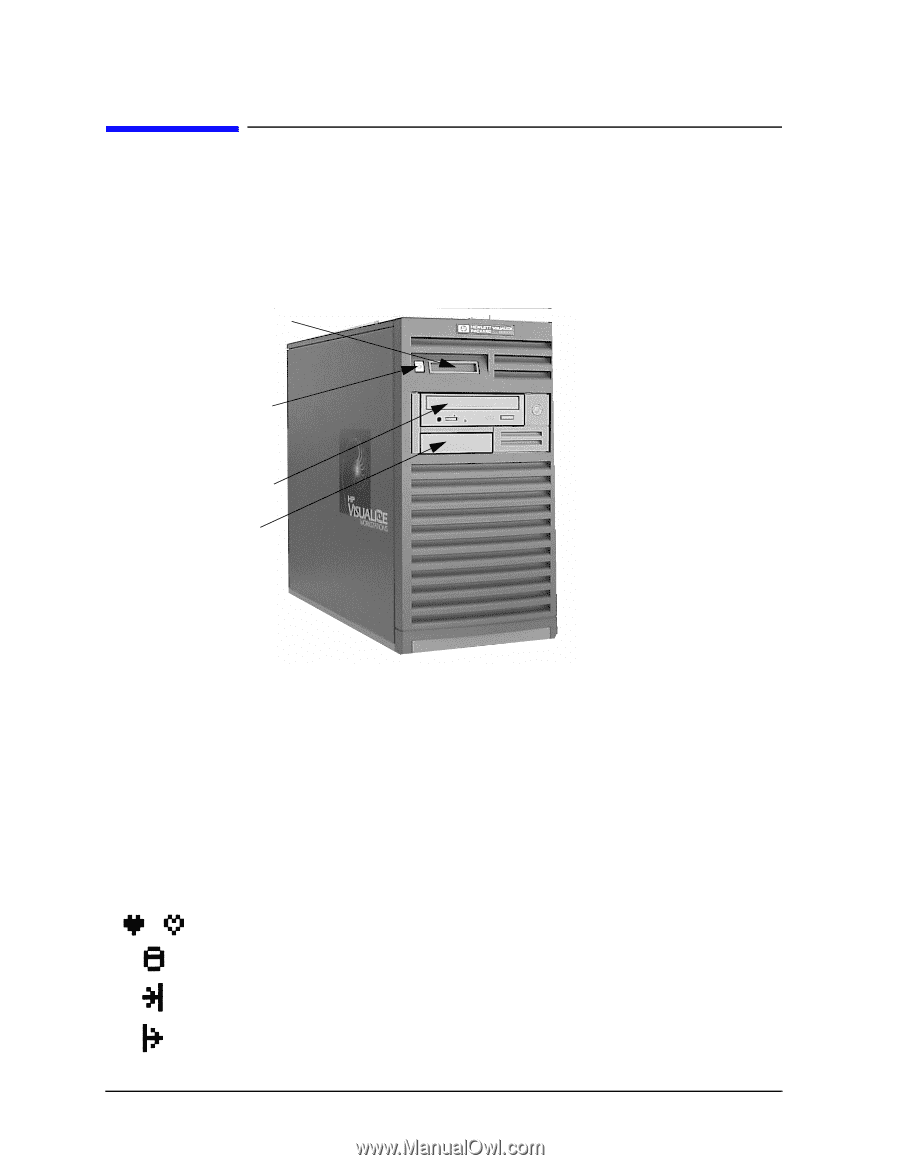
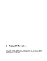
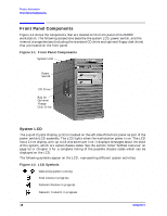
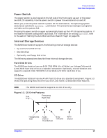
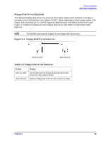
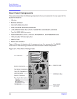
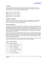
Product Information Front Panel Components Front Panel Components Figure 1-1 shows the components that are located on the front panel of the B2000 workstation. The following subsections describe the system LCD, power switch, and the internal storage devices (including the standard CD drive and optional floppy disk drive) that are located on the front panel. Figure 1-1. Front Panel Components System LCD Power Switch CD Drive Bay for Optional Floppy Disk Drive System LCD The Liquid Crystal Display (LCD) is located on the left side of the front panel as part of the power switch/LCD assembly. The LCD lights when the workstation power is on. The LCD has a 2-line display, with up to 16-characters per line. It displays messages about the state of the system, which are called chassis codes. See the section titled "Selftest Failures" on page 53 in Chapter 3 for a complete listing of the possible chassis codes which can be displayed on the LCD. The following symbols appear on the LCD, representing different system activities. Figure 1-2. LCD Symbols Operating system running Disk Access in progress Network Receive in progress Network Transmit in progress 18 Chapter 1
-
 1
1 -
2
-
3
-
4
-
5
-
6
-
7
-
8
-
9
-
10
-
11
-
12
-
 13
13 -
 14
14 -
 15
15 -
 16
16 -
 17
17 -
 18
18 -
 19
19 -
 20
20 -
 21
21 -
 22
22 -
 23
23 -
24
-
25
-
26
-
27
-
28
-
29
-
30
-
31
-
32
-
33
-
34
-
35
-
36
-
37
-
38
-
39
-
40
-
41
-
42
-
43
-
44
-
45
-
46
-
47
-
48
-
49
-
50
-
51
-
52
-
53
-
54
-
55
-
56
-
57
-
58
-
59
-
60
-
61
-
62
-
63
-
64
-
65
-
66
-
67
-
68
-
69
-
70
-
71
-
72
-
73
-
74
-
75
-
76
-
77
-
78
-
79
-
80
-
81
-
82
-
83
-
84
-
85
-
86
-
87
-
88
-
89
-
90
-
91
-
92
-
93
-
94
-
95
-
96
-
97
-
98
-
99
-
100
-
101
-
102
-
103
-
104
-
105
-
106
-
107
-
108
-
109
-
110
-
111
-
112
-
113
-
114
-
115
-
116
-
117
-
118
-
119
-
120
-
121
-
122
-
123
-
124
-
125
-
126
-
127
-
128
-
129
-
130
-
131
-
132
-
133
-
134
-
135
-
136
-
137
-
138
-
139
-
140
-
141
-
142
-
143
-
144
-
145
-
146
-
147
-
148
-
149
-
150
-
151
-
152
-
153
-
154
-
155
-
156
-
157
-
158
-
159
-
160
-
161
-
162
-
163
-
164
-
165
-
166
-
167
-
168
-
169
-
170
-
171
-
172
-
173
-
174
-
175
-
176
-
177
-
178
-
179
-
180
-
181
-
182
-
183
-
184
-
185
-
186
-
187
-
188
-
189
-
190
-
191
-
192
-
193
-
194
-
195
-
196
-
197
-
198
-
199
-
200
-
201
-
202
-
203
-
204
 |
 |