HP Xw25p ProLiant BL25p Server Blade Maintenance and Service Guide
HP Xw25p - ProLiant - Blade Workstation Manual
 |
View all HP Xw25p manuals
Add to My Manuals
Save this manual to your list of manuals |
HP Xw25p manual content summary:
- HP Xw25p | ProLiant BL25p Server Blade Maintenance and Service Guide - Page 1
HP ProLiant BL25p Server Blade Maintenance and Service Guide December 2005 (Fourth Edition) Part Number 377851-004A - HP Xw25p | ProLiant BL25p Server Blade Maintenance and Service Guide - Page 2
Micro Devices, Inc. December 2005 (Fourth Edition) Part Number 377851-004A Audience assumptions This guide is for an experienced service technician. HP assumes you are qualified in the servicing of computer equipment and trained in recognizing hazards in products with hazardous energy levels and are - HP Xw25p | ProLiant BL25p Server Blade Maintenance and Service Guide - Page 3
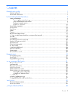
and cautions ...9 Symbols on equipment ...10 Server blade preparation ...11 Access panel ...12 Hard drives ...12 DIMMs...13 Processor ...14 HP Smart Array 6i Controller ...17 HP Smart Array 6i battery-backed write cache enabler (optional 18 Air baffle ...18 Fan assembly...19 Fibre Channel mezzanine - HP Xw25p | ProLiant BL25p Server Blade Maintenance and Service Guide - Page 4
Index...42 Contents 4 - HP Xw25p | ProLiant BL25p Server Blade Maintenance and Service Guide - Page 5
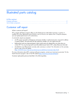
to send the defective part back to HP, unless otherwise instructed. • Available for most HP products currently under warranty or contract. For information on the warranty service, refer to the HP website (http://h18004.www1.hp.com/products/servers/platforms/warranty/index.html). For more information - HP Xw25p | ProLiant BL25p Server Blade Maintenance and Service Guide - Page 6
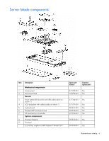
Server blade components Item Description Mechanical components 1 Access panel 2 Hard drive blank Boards 3 Power button/LED board kit with LED cable (cable not shown *) 4 SCSI backplane with cables (cables not shown *) 5 System board 6 Standard NIC mezzanine card 7 HP Smart Array 6i - HP Xw25p | ProLiant BL25p Server Blade Maintenance and Service Guide - Page 7
blade return kit * 17 Local I/O cable * Memory 18 DIMM, 512 MB, PC-3200 DDR SDRAM *1 19 DIMM, 1 GB, PC-3200 DDR SDRAM *1 20 DIMM, 2 GB, PC-3200 DDR SDRAM *1 21 DIMM, 4 GB, PC-3200 DDR SDRAM *1 Options 22 FC mezzanine a) Emulex-based Fibre Channel Mezzanine for HP p-Class BladeSystem - HP Xw25p | ProLiant BL25p Server Blade Maintenance and Service Guide - Page 8
Server blade preparation ...11 Access panel ...12 Hard drives ...12 DIMMs...13 Processor ...14 HP Smart Array 6i Controller ...17 HP Smart Array 6i battery-backed write cache enabler (optional 18 Air baffle...18 Server blade bay blank...28 Safety considerations Before performing service workstations - HP Xw25p | ProLiant BL25p Server Blade Maintenance and Service Guide - Page 9
reduce the risk of injury from high-current electrical energy, do not remove the server blade access panel when power is applied through the HP ProLiant p-Class diagnostic station. Remove all power from the server blade before removing the access panel. WARNING: To reduce the risk of shock or injury - HP Xw25p | ProLiant BL25p Server Blade Maintenance and Service Guide - Page 10
the server blade for long periods with the access panel open or removed. Operating the server blade in or electric shock hazards. Refer all servicing to qualified personnel. WARNING: To reduce health and safety requirements and guidelines for manual material handling. These symbols, on power - HP Xw25p | ProLiant BL25p Server Blade Maintenance and Service Guide - Page 11
removal procedure. Server blades are set to power up automatically upon insertion. If you have changed this setting, use the power button or iLO Virtual Power Button feature to power up the server blade. For more information about iLO, refer to the HP Integrated Lights-Out User Guide. Removal and - HP Xw25p | ProLiant BL25p Server Blade Maintenance and Service Guide - Page 12
remove the component: 1. Power down the server blade and remove it from the server blade enclosure ("Server blade preparation" on page 11). 2. Loosen CAUTION: To prevent improper cooling and thermal damage, do not operate the server unless all bays are populated with either a component or a blank. - HP Xw25p | ProLiant BL25p Server Blade Maintenance and Service Guide - Page 13
and remove it from the server blade enclosure ("Server blade preparation" on page 11). 2. Remove the access panel ("Access panel" on page 12). 3. Open the DIMM slot latches. 4. Remove the DIMM from the slot. CAUTION: Use only HP DIMMs. DIMMs from other sources may adversely affect data integrity - HP Xw25p | ProLiant BL25p Server Blade Maintenance and Service Guide - Page 14
memory bank 2 Processor 2 memory bank 1 Processor 2 memory bank 2 Processor To remove the component: 1. Power down the server blade and remove it from the server blade enclosure ("Server blade preparation" on page 11). 2. Remove the access panel ("Access panel" on page 12). Removal and replacement - HP Xw25p | ProLiant BL25p Server Blade Maintenance and Service Guide - Page 15
processor is designed to fit one way into the socket. Use the alignment guides on the processor and socket to properly align the processor with the socket. Refer to the server blade hood label for specific instructions. 2. Close the processor locking lever. CAUTION: Be sure that the processor socket - HP Xw25p | ProLiant BL25p Server Blade Maintenance and Service Guide - Page 16
3. Remove the protective cover from the thermal interface. CAUTION: After the cover is removed, do not touch the thermal interface media. IMPORTANT: The heatsink is not reusable and must be discarded if removed from the processor after application. 4. Insert the heatsink and close the processor cage - HP Xw25p | ProLiant BL25p Server Blade Maintenance and Service Guide - Page 17
cooling, be sure the correct processor air baffle (on page 18) is installed at all times. HP Smart Array 6i Controller To remove the component: 1. Power down the server blade and remove it from the server blade enclosure ("Server blade preparation" on page 11). 2. Remove the access panel ("Access - HP Xw25p | ProLiant BL25p Server Blade Maintenance and Service Guide - Page 18
HP Smart Array 6i battery-backed write cache enabler (optional) To remove the component: 1. Power down the server blade and remove it from the server blade enclosure ("Server blade : 1. Power down the server blade and remove it from the server blade enclosure ("Server blade preparation" on page 11). - HP Xw25p | ProLiant BL25p Server Blade Maintenance and Service Guide - Page 19
proper cooling, be sure the correct processor air baffle (on page 18) is installed at all times. Fan assembly To remove the component: 1. Power down the server blade and remove it from the server blade enclosure ("Server blade preparation" on page 11). 2. Remove the access panel ("Access panel" on - HP Xw25p | ProLiant BL25p Server Blade Maintenance and Service Guide - Page 20
FC support (for clustering capabilities) and SAN connection when used in conjunction with the RJ-45 Patch Panel 2 or the GbE2 Interconnect Switch with FC pass-through option. The card is installed on top of the standard NIC mezzanine card. To remove the component: 1. Power down the server blade and - HP Xw25p | ProLiant BL25p Server Blade Maintenance and Service Guide - Page 21
to the label on the FC mezzanine to verify compatibility with the server blade. Standard NIC mezzanine card To remove the component: 1. Power down the server blade and remove it from the server blade enclosure ("Server blade preparation" on page 11). 2. Remove the access panel ("Access panel" on - HP Xw25p | ProLiant BL25p Server Blade Maintenance and Service Guide - Page 22
NOTE: The air baffle is most easily removed at a 45° angle. 8. Grasp the SCSI backplane on the left side when facing the rear of the server blade and lift slightly to rotate the SCSI backplane out. 9. Lift the SCSI backplane out of the chassis. To replace the component, reverse the removal procedure - HP Xw25p | ProLiant BL25p Server Blade Maintenance and Service Guide - Page 23
and remove it from the server blade enclosure ("Server blade preparation" on page 11). 2. Remove the access panel ("Access panel" on page 12). 3. Remove the thumbscrews on the back of the chassis to release the power connector. NOTE: The power connector will not push completely into the chassis - HP Xw25p | ProLiant BL25p Server Blade Maintenance and Service Guide - Page 24
Release the latches and lift the DC filter module away from the system board while pushing the power connector into the chassis. To replace the component, reverse the removal procedure. Power button/LED board To remove the component: 1. Power down the server blade and remove it from the server blade - HP Xw25p | ProLiant BL25p Server Blade Maintenance and Service Guide - Page 25
removal procedure. System board battery If the server blade no longer automatically displays the correct date and time, you may need to replace the HP Partner, or their agents. For more information about battery replacement or proper disposal, contact an authorized reseller or an authorized service - HP Xw25p | ProLiant BL25p Server Blade Maintenance and Service Guide - Page 26
("Server blade preparation" on page 11). 2. Remove the access panel ("Access panel" on page 12). 3. Remove the DIMMs ("DIMMs" on page 13). 4. Remove the processor and heatsinks ("Processor" on page 14). 5. Remove the fan assembly ("Fan assembly" on page 19). 6. Remove the array controller ("HP - HP Xw25p | ProLiant BL25p Server Blade Maintenance and Service Guide - Page 27
13. Disconnect the LED cable from the system board before removing the system board from the server blade. 14. Slide the system board toward the front of the server blade. 15. Lift the system board until it comes off the alignment keys. 16. Lift the edge of the system board nearest the system - HP Xw25p | ProLiant BL25p Server Blade Maintenance and Service Guide - Page 28
enclosure. CAUTION: To prevent improper cooling and thermal damage, do not operate the server blade enclosure unless all bays are populated with either a component or a blank. To replace a server blade blank, align the blank with the empty bay and slide it in until the blank is fully seated. Removal - HP Xw25p | ProLiant BL25p Server Blade Maintenance and Service Guide - Page 29
in both offline and online versions, that provides diagnostics and troubleshooting capabilities to assist IT administrators who verify server blade installations, troubleshoot problems, and perform repair validation. HP Insight Diagnostics Offline Edition performs various in-depth system and - HP Xw25p | ProLiant BL25p Server Blade Maintenance and Service Guide - Page 30
• For Linux: IML Viewer Application • From within the iLO user interface • From within HP Insight Diagnostics (on page 29) For more information, refer to the Management CD in the HP ProLiant Essentials Foundation Pack. Diagnostic tools 30 - HP Xw25p | ProLiant BL25p Server Blade Maintenance and Service Guide - Page 31
Server component identification In this section Front panel components ...31 Front panel LEDs ...32 Rear plug SCSI hard drive bay 2 4 I/O port* * The I/O port is used with the local I/O cable to perform some server blade configuration and diagnostic procedures. Server component identification 31 - HP Xw25p | ProLiant BL25p Server Blade Maintenance and Service Guide - Page 32
link or activity Green = On Amber = Standby (auxiliary power available) Off = Off Green/Flashing = Activity Off = No activity Flashing = Online activity Off = No online activity Server component identification 32 - HP Xw25p | ProLiant BL25p Server Blade Maintenance and Service Guide - Page 33
status Status Flashing = Fault process activity Off = No fault process activity * Actual NIC numeration depends on several factors, including the operating system installed on the server blade. Rear panel components Item Description 1 Power connector 2 Signal connector - HP Xw25p | ProLiant BL25p Server Blade Maintenance and Service Guide - Page 34
board connector 12 SCSI backplane board connector 1 13 Processor socket 1 (shown populated) 14 DIMMs 1-4 15 Processor 1 memory bank 1(shown populated) 16 Processor 1 memory bank 2 17 HP Smart Array 6i Battery-Backed Write Cache Enabler (optional) Server component identification 34 - HP Xw25p | ProLiant BL25p Server Blade Maintenance and Service Guide - Page 35
Item Description 18 HP Smart maintenance switch procedures When you perform troubleshooting steps, this guide may instruct you to perform the following procedures: access panel. 5. Connect the server blade to system power and power up the server blade ("Server blade preparation" on page 11). - HP Xw25p | ProLiant BL25p Server Blade Maintenance and Service Guide - Page 36
ROM are corrupt, you must return the system board for a service replacement. Local I/O cable Item Connector 1 Local I/O 2 Video 3 USB 1 4 USB 2 5 Serial Description For connecting to the local I/O port on the server blade front panel For connecting a video monitor For connecting a USB - HP Xw25p | ProLiant BL25p Server Blade Maintenance and Service Guide - Page 37
Item Connector Description 6 iLO RJ-45 For connecting an Ethernet to the server blade (10/100 Ethernet) iLO interface from a client device Hot-plug SCSI hard drive LEDs Item LED or a drive capacity upgrade is in progress, you may replace the drive online. Server component identification 37 - HP Xw25p | ProLiant BL25p Server Blade Maintenance and Service Guide - Page 38
part of an array being selected by an array configuration utility • Drive Identification has been selected in HP SIM • The drive firmware is being updated The drive has been placed offline due to hard disk to an array controller, you may replace the drive online. Server component identification 38 - HP Xw25p | ProLiant BL25p Server Blade Maintenance and Service Guide - Page 39
Storage maximum humidity of 95% is based on a maximum temperature of 45°C (113°F). Altitude maximum for storage corresponds to a pressure minimum of 70 KPa. Server specifications Specification Height Depth Width Weight (maximum) Value 4.29 cm (1.69 in) 71.1 cm (28.00 in) 26.14 cm (10.29 in) 9.43 - HP Xw25p | ProLiant BL25p Server Blade Maintenance and Service Guide - Page 40
Acronyms and abbreviations BBWC battery-backed write cache BIOS Basic Input/Output System DDR double data rate ESD electrostatic discharge FC Fibre Channel I/O input/output iLO Integrated Lights-Out IML Integrated Management Log IP Internet Protocol LED light-emitting diode NIC network interface - HP Xw25p | ProLiant BL25p Server Blade Maintenance and Service Guide - Page 41
PSP ProLiant Support Pack RBSU ROM-Based Setup Utility RILOE Remote Insight Lights-Out Edition ROM read-only memory SA Smart Array SCSI small computer system interface SIM - HP Xw25p | ProLiant BL25p Server Blade Maintenance and Service Guide - Page 42
backed write cache battery pack 34 battery-backed write cache enabler 17, 18, 34 buttons 31 C cable connector identification 36 cables 36 cabling 36 hard drives, installing 12 health driver 37 health LEDs 37 heatsink 14 HP Insight Diagnostics 29 12, 37 I illustrated parts catalog 5 iLO connector - HP Xw25p | ProLiant BL25p Server Blade Maintenance and Service Guide - Page 43
and replacement procedures 8 S safety considerations 8 SCSI backplane 22 serial port 36 server blade bay blank 28 server, rear panel components 33 Smart Array 6i Controller 17 specifications 39 specifications, server 39 Standby mode 11 static electricity 8 Survey Utility 29 symbols on equipment 10
-
 1
1 -
 2
2 -
 3
3 -
 4
4 -
 5
5 -
 6
6 -
 7
7 -
8
-
9
-
10
-
11
-
12
-
13
-
14
-
15
-
16
-
17
-
18
-
19
-
20
-
21
-
22
-
23
-
24
-
25
-
26
-
27
-
28
-
29
-
30
-
31
-
32
-
33
-
34
-
35
-
36
-
37
-
38
-
39
-
40
-
41
-
42
-
43
 |
 |

HP ProLiant BL25p Server Blade
Maintenance and Service Guide
December 2005 (Fourth Edition)
Part Number 377851-004A