HP rp5400 Troubleshooting and Build-Up Procedures Product Update - rp5400, rp5 - Page 4
System Will Not Power On to Standby Mode, System Will Not Power On or Remain Powered On,
 |
View all HP rp5400 manuals
Add to My Manuals
Save this manual to your list of manuals |
Page 4 highlights
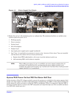
rp5400, rp5430, rp5450 and rp5470 Troubleshooting and Build-Up Procedures System Will Not Power On to Standby Mode problem. Therefore fully analyze the GSP error log contents associated with the power-off condition. Occasionally the error logs do not have any relevant entries or may not point to any specific condition-for instance only specifying a high voltage DC undervoltage condition. In this case go to the problem statement in this document that best describes the symptom and follow the troubleshooting steps in order. System Will Not Power On to Standby Mode If the system will not power on to standby mode, follow these troubleshooting steps. These troubleshooting hints are for standby mode (power switch OFF). 1. Check voltage: +48vdc and +15vdc. • +48vdc. The power supplies are creating +48vdc output if the power supply LED on the power supply module(s) is solid green. The +48vdc is measured at pins 2, 4 and 5 (Figure 1-1 on page 5) of power converter output J39. NOTE Measuring voltages at J39 while it is connected to the system board requires a voltmeter probe with a sharp tip about one inch long to contact the crimp terminals. • +15vdc (housekeeping voltage). The housekeeping voltage is present when the power LED on the front panel is blinking green. The housekeeping voltage is present when the power LED on the platform monitor is blinking green. The +15vdc is measured at pin 1 (Figure 1-1 on page 5) of power converter output J39 and at the V15 testpoint on the platform monitor. 2. Reduce the system to the minimum power configuration for standby mode (+48vdc and +15vdc voltages): power supply 0, the power converter, and the system board. Replace these field replaceable units (FRUs) individually or all at once until the voltages are present. System Will Not Power On or Remain Powered On These are troubleshooting hints for failure to power on. 1. Ensure standby mode voltages are present. • Turn the power switch on. In addition to +48vdc and +15vdc standby voltages, the +12vdc, +5.1vdc, and +3.3vdc should be present. • +12vdc. The +12vdc voltage is present if the embedded disks have power. Examine green power LED on embedded disks. This LED should momentarily illuminate after the power switch has been turned on. The +12vdc is measured at pins 3 and 6 (Figure 1-1 on page 5) of power converter output J39. • +5.1vdc. This voltage cannot be verified by observing LEDs. The +5.1vdc is measured between bus bar contacts J37 and J38 (Figure 1-1 on page 5) on the system board and at the V5B testpoint on the platform monitor. • +3.3vdc. This voltage cannot be verified by observing LEDs. The +3.3vdc is measured between bus bar contacts J35 and J36 (Figure 1-1 on page 5) on the system board. 4 Chapter 1
-
 1
1 -
 2
2 -
 3
3 -
 4
4 -
 5
5 -
 6
6 -
 7
7 -
 8
8
 |
 |
