HP rp5400 Troubleshooting and Build-Up Procedures Product Update - rp5400, rp5 - Page 5
System Will Power On but Will Not Enter Self-Test, Power Supply Test Points
 |
View all HP rp5400 manuals
Add to My Manuals
Save this manual to your list of manuals |
Page 5 highlights
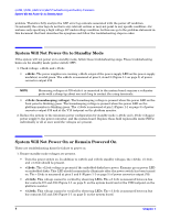
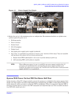
rp5400, rp5430, rp5450 and rp5470 Troubleshooting and Build-Up Procedures System Will Power On but Will Not Enter Self-Test Figure 1-1 Power Supply Test Points 2. Reduce the server to the minimum power-on configuration. The minimum hardware an rp54xx series system requires for power on is: • Platform monitor • Power converter • System board • PCI I/O backplane • Display board • Any single power supply (power supply 0 preferred) • Any 7 fans (it is probably not necessary to remove a fan-however if fewer than 7 fans are installed and functional, the system will not remain powered up). a. Replace these FRUs individually or all at once to get the system to power up. b. Add remaining FRUs until system is complete. NOTE When adding processors, be sure to install the processor support modules first. If processors are installed but the corresponding processor support module is not installed, the system will not power up. A system alert that describes a faulty processor support module 0 or 1 is generated. System Will Power On but Will Not Enter Self-Test In this situation, all the DC voltages needed to operate the system are available but the system appears dead. In this case, there will be very little useful information available from any LEDs or other physical indicators on the system. It will be necessary to utilize the GSP to troubleshoot. Thus, it is imperative that the GSP is functional and that there is access to the GSP commands and output through any of the available interfaces (e.g. GSP LAN, console port, etc.). Chapter 1 5
-
 1
1 -
 2
2 -
 3
3 -
 4
4 -
 5
5 -
 6
6 -
 7
7 -
 8
8
 |
 |
