HP rp5400 Troubleshooting and Build-Up Procedures Product Update - rp5400, rp5 - Page 6
System Will Power On but Will Not Enter Self-Test, Processor 3/Runway terminator, and PSM0. - cpu
 |
View all HP rp5400 manuals
Add to My Manuals
Save this manual to your list of manuals |
Page 6 highlights
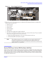
rp5400, rp5430, rp5450 and rp5470 Troubleshooting and Build-Up Procedures System Will Power On but Will Not Enter Self-Test Once access to the GSP is made available, the actual status of the system can be obtained through the GSP's virtual front panel (VFP) command. If problems exist with the runway bus, the system will power on but the CPU(s) will not enter self-test. Checking the VFP at this point will show the following: GSP> vfp VFP This command activates the immediate display of the virtual front panel. LEDs: RUN ATTENTION FAULT REMOTE POWER OFF FLASH OFF ON ON LED State: No code is executing. Non-critical error detected. Check Chassis and Console Logs for error messages. power monitor 4400 Decoding the 4400 chassis code as a platform monitor code translates to: • Source -> 4 = power • Caller Activity -> 4 = monitor Assuming that the reporting entity type is platform monitor, then the caller activity would also be monitor: • Caller Subactivity -> 00 = unspecified. This chassis code indicates that the CPU failed to enter self-test due to a system power problem. Since the fans turned on and stayed on, the power supply subsystem is obviously functional. The chassis code does not provide sufficient information for this condition. The recommendation on troubleshooting an rp54xx series system that fails to enter CPU self-test with a VFP self-test chassis code of 4400 (or simply does not seem to enter self-test) is to concentrate on the runway components. On an rp54xx series system the main runway components are the processors (and their associated processor support modules [PSMs]) and the system card. An rp54xx series system must have a minimum of 2 functioning processors installed-in the processor 0 and processor 3 locations-before the runway bus is functional and the processors will begin to execute self-test code. On a 1-way system, there must be a processor module in position 0 and a runway terminator (P/N A5570-62014) assembly in processor position 3. There must also be a processor support module power supply in PSM0 position. On systems with more than 2 processors installed, it is best to remove all but processors 0 and 3 and retest. If the system board is equipped with a processor power dipswitch (e.g. dipswitch S3 on an rp5430 or rp5470), try disabling processors 1 and 2 by placing switch 2 and 3 on dipswitch S3 to off. Next, try replacing PSM0. Then replace one or both processors (or alternatively replace processor 3 with a runway terminator). A faulty runway terminator may also prevent the system from entering self-test. As a final alternative, replace the system card. In this situation, replacing parts other than those associated with the system runway bus is typically not necessary. The minimum system configuration needed to have an rp54xx series system initiate self-test code is the same as for the minimum power on configuration above with the addition of the core GSP board (so that the GSP's VFP command can be executed and monitored), Processor 0, Processor 3/Runway terminator, and PSM0. 6 Chapter 1
-
 1
1 -
 2
2 -
 3
3 -
 4
4 -
 5
5 -
 6
6 -
 7
7 -
 8
8
 |
 |
