HP t200 HP Compaq MultiSeat ms6200 Desktop Hardware Reference Guide
HP t200 Manual
 |
View all HP t200 manuals
Add to My Manuals
Save this manual to your list of manuals |
HP t200 manual content summary:
- HP t200 | HP Compaq MultiSeat ms6200 Desktop Hardware Reference Guide - Page 1
Hardware Reference Guide HP Compaq MultiSeat ms6200 Desktop - HP t200 | HP Compaq MultiSeat ms6200 Desktop Hardware Reference Guide - Page 2
without notice. Microsoft, Windows, and MultiPoint are either trademarks or registered trademarks of Microsoft Corporation in the United States and/or other countries. The only warranties for HP products and services are set forth in the express warranty statements accompanying such products and - HP t200 | HP Compaq MultiSeat ms6200 Desktop Hardware Reference Guide - Page 3
About This Book This guide provides basic information for upgrading this computer model. WARNING! Text set off in this manner indicates that failure to follow directions could result in bodily - HP t200 | HP Compaq MultiSeat ms6200 Desktop Hardware Reference Guide - Page 4
iv About This Book - HP t200 | HP Compaq MultiSeat ms6200 Desktop Hardware Reference Guide - Page 5
Number Location ...7 2 Hardware Upgrades ...8 Serviceability Features ...8 Warnings and Cautions ...8 Removing Installing DIMMs ...17 Removing or Installing an Expansion Card 20 Drive Positions ...24 Installing and Removing Drives 25 Removing a 5.25-inch Drive from a Drive Bay 27 Installing - HP t200 | HP Compaq MultiSeat ms6200 Desktop Hardware Reference Guide - Page 6
Appendix C Installing a Security Lock 45 HP/Kensington MicroSaver Security Cable Lock 45 Padlock ...46 HP Business PC Security Lock 47 Front Bezel Security ...51 Appendix D Electrostatic Discharge 53 Preventing Electrostatic Damage 53 Grounding Methods ...53 Appendix E Computer Operating - HP t200 | HP Compaq MultiSeat ms6200 Desktop Hardware Reference Guide - Page 7
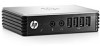
software installed in the computer, run the diagnostic utility (included on some computer models only). NOTE: The MultiSeat Desktop can also be used in a tower orientation. For more information, see Changing from Desktop to Tower Configuration on page 13 in this guide. Figure 1-1 HP Compaq MultiSeat - HP t200 | HP Compaq MultiSeat ms6200 Desktop Hardware Reference Guide - Page 8
8 3.5-inch Media Card Reader (optional)2 4 Dual-State Power Button 9 Hard Drive Activity Light 5 Power On Light 10 Headphone Connector NOTE: The Power On Light is normally green when the power is on. If it is flashing red, there is a problem with the computer and it is displaying a diagnostic - HP t200 | HP Compaq MultiSeat ms6200 Desktop Hardware Reference Guide - Page 9
Media Card Reader Activity Light 4 SD/MMC+/miniSD ● Secure Digital (SD) ● Secure Digital High Capacity (SDHC) ● MiniSD ● MicroSDHC ● MiniSDHC ● (MMC Plus) ● Reduced Size MultiMediaCard 4.0 (MMC Mobile) ● MMC Micro (adapter required) ● MicroDrive ● Memory Stick PRO Duo (MS PRO Duo) ● Memory - HP t200 | HP Compaq MultiSeat ms6200 Desktop Hardware Reference Guide - Page 10
Figure 1-4 Rear Panel Components Table 1-3 Rear Panel Components 1 RJ-45 Network Connector 6 2 Serial Connector 7 3 PS/2 Mouse Connector (green) 8 4 Power Cord Connector 9 5 Universal Serial Bus (USB) 10 NOTE: Arrangement and number of connectors may vary by model. DisplayPort - HP t200 | HP Compaq MultiSeat ms6200 Desktop Hardware Reference Guide - Page 11
keyboard settings (Num Lock, Caps Lock, and Scroll Lock). 4 Numeric Keys Work like a calculator keypad. 5 Arrow Keys Used to navigate through a document or Web site. These keys allow you to move left, right, up, and down, using the keyboard instead of the mouse. 6 Ctrl Keys Used in combination - HP t200 | HP Compaq MultiSeat ms6200 Desktop Hardware Reference Guide - Page 12
page 5 to identify the Windows Logo key. Table 1-5 Windows Logo Key Functions The following Windows Logo Key functions are available in Windows MultiPoint™ Server 2011. Windows Logo Key Displays or hides the Start menu Windows Logo Key + d Displays the Desktop Windows Logo Key + m Minimizes - HP t200 | HP Compaq MultiSeat ms6200 Desktop Hardware Reference Guide - Page 13
Serial Number Location Each computer has a unique serial number and product ID number in the location shown below. Keep these numbers available for use when contacting customer service for assistance. Figure 1-6 Serial Number and Product ID Location Serial Number Location 7 - HP t200 | HP Compaq MultiSeat ms6200 Desktop Hardware Reference Guide - Page 14
make it easy to upgrade and service. No tools are needed for most of the installation procedures described in this chapter. Warnings and Cautions Before performing upgrades be sure to carefully read all of the applicable instructions, cautions, and warnings in this guide. WARNING! To reduce the risk - HP t200 | HP Compaq MultiSeat ms6200 Desktop Hardware Reference Guide - Page 15
state, voltage is always present on the system board as long as the system is plugged into an active AC outlet. You must disconnect the power cord to avoid damage to the internal components of the computer. 5. If the computer is on a stand, remove the computer from the stand and lay - HP t200 | HP Compaq MultiSeat ms6200 Desktop Hardware Reference Guide - Page 16
the Computer Access Panel Slide the lip on the front end of the access panel under the lip on the front of the chassis (1) then press the back end of the access panel onto the unit so that it locks into place (2). Figure 2-2 Replacing the Computer Access Panel 10 Chapter 2 Hardware - HP t200 | HP Compaq MultiSeat ms6200 Desktop Hardware Reference Guide - Page 17
long as the system is plugged into an active AC outlet. You must disconnect the power cord to avoid damage to the internal components of the computer. 5. If the computer -inch drive bays that need to be removed before installing a drive. To remove a bezel blank: 1. Remove the access panel and front - HP t200 | HP Compaq MultiSeat ms6200 Desktop Hardware Reference Guide - Page 18
2. To remove a bezel blank, push the two retaining tabs that hold the bezel blank in place towards the outer right edge of the bezel (1) and slide the bezel blank back and to the right to remove it (2). Figure 2-4 Removing a Bezel Blank Replacing the Front Bezel Insert the three hooks on the bottom - HP t200 | HP Compaq MultiSeat ms6200 Desktop Hardware Reference Guide - Page 19
stand. Figure 2-6 Changing from Desktop to Tower Orientation NOTE: To stabilize the computer in a tower orientation, HP recommends the use of the optional tower stand. 6. Reconnect the power cord and any external devices, then turn on the computer. NOTE: Ensure at least 10.2 centimeters (4 inches - HP t200 | HP Compaq MultiSeat ms6200 Desktop Hardware Reference Guide - Page 20
System Board Connector System Board Label Color 1 DIMM4 (Channel A) DIMM4 white DIMM1 (Channel B) DIMM1 black 5 Power SATAPWR0 black 6 Power SATAPWR1 7 SATA 3.0 SATA0 dark 2nd Optical Drive if an eSATA Adapter Cable exists 1st Optical Drive eSATA Adapter Cable, or 2nd Optical Drive - HP t200 | HP Compaq MultiSeat ms6200 Desktop Hardware Reference Guide - Page 21
Color 16 Hood Sensor HSENSE white 17 PCI Express x1 X1PCIEXP1 black 18 PCI Express x1 X4PCIEXP black 19 PCI Express x16 X16PCIEXP black 20 PCI PCI white Component Hood Sensor Expansion Card Expansion Card Expansion Card Expansion Card Installing product DOES NOT support DDR3 Ultra - HP t200 | HP Compaq MultiSeat ms6200 Desktop Hardware Reference Guide - Page 22
in memory channel A. The system will automatically operate in single channel mode, dual channel mode, or flex mode, depending on how the DIMMs are installed. ● The system will operate in single channel mode if the DIMM sockets are populated in one channel only. ● The system will operate in a higher - HP t200 | HP Compaq MultiSeat ms6200 Desktop Hardware Reference Guide - Page 23
Installing DIMMs CAUTION: You must disconnect the power cord and wait approximately 30 seconds for the power to drain before adding or removing memory modules. Regardless of the power-on state, voltage is always supplied to the memory modules as long as the computer is plugged into an active AC - HP t200 | HP Compaq MultiSeat ms6200 Desktop Hardware Reference Guide - Page 24
the Drive Cage Up 8. Open both latches of the memory module socket (1), and insert the memory module into the socket (2). Figure 2-9 Installing a DIMM NOTE: A memory module can be installed in only one way. Match the notch on the module with the tab on the memory socket. Populate the black DIMM - HP t200 | HP Compaq MultiSeat ms6200 Desktop Hardware Reference Guide - Page 25
are in the closed position (3). 10. Repeat steps 8 and 9 to install any additional modules. 11. Replace the access panel. 12. If the computer was on a stand, replace the stand. 13. Reconnect the power cord and turn on the computer. 14. Lock any security devices that - HP t200 | HP Compaq MultiSeat ms6200 Desktop Hardware Reference Guide - Page 26
x16 expansion slot. NOTE: The PCI and PCI Express slots support only low profile cards. You can install a PCI Express x1, x4, x8, or x16 expansion card the system is plugged into an active AC outlet. You must disconnect the power cord to avoid damage to the internal components of the computer. 5. If - HP t200 | HP Compaq MultiSeat ms6200 Desktop Hardware Reference Guide - Page 27
card, remove the expansion slot cover or the existing expansion card. NOTE: Before removing an installed expansion card, disconnect any cables that may be attached to the expansion card. a. If you are installing an expansion card in a vacant socket, remove the appropriate expansion slot cover on the - HP t200 | HP Compaq MultiSeat ms6200 Desktop Hardware Reference Guide - Page 28
b. If you are removing a standard PCI card or PCI Express x1 card, hold the card at each end, and carefully rock it back and forth until the connectors pull free from the socket. Pull the expansion card straight up from the socket (1) then away from the inside of the chassis to release it from the - HP t200 | HP Compaq MultiSeat ms6200 Desktop Hardware Reference Guide - Page 29
card is aligned with the open slot on the rear of the chassis. Press the card straight down into the expansion socket on the system board (2). Figure 2-14 Installing an Expansion Card NOTE: When installing an expansion card, press firmly on the card so that the whole connector seats properly in the - HP t200 | HP Compaq MultiSeat ms6200 Desktop Hardware Reference Guide - Page 30
installed card, if needed. Connect internal cables to the system board, if needed. 15. Replace the computer access panel. 16. If the computer was on a stand, replace the stand. 17. Reconnect the power of the storage devices installed in the computer, run Computer Setup. 24 Chapter 2 Hardware Upgrades - HP t200 | HP Compaq MultiSeat ms6200 Desktop Hardware Reference Guide - Page 31
optional eSATA adapter cable to ● The power cable for HP-supplied metric screws are black and the HP-supplied standard screws are silver. If you are replacing the primary hard drive, you must remove the four silver and blue 6-32 isolation mounting guide screws from the old hard drive and install - HP t200 | HP Compaq MultiSeat ms6200 Desktop Hardware Reference Guide - Page 32
to the computer or drive: If you are inserting or removing a drive, shut down the operating system properly, turn off the computer, and unplug the power cord. Do not remove a drive while the computer is on or in standby mode. Before handling a drive, ensure that you are discharged of static - HP t200 | HP Compaq MultiSeat ms6200 Desktop Hardware Reference Guide - Page 33
. 4. Disconnect the power cord from the power outlet and disconnect any external devices. CAUTION: Regardless of the power-on state, voltage is as the system is plugged into an active AC outlet. You must disconnect the power cord to avoid damage to the internal components of the computer. 5. If the - HP t200 | HP Compaq MultiSeat ms6200 Desktop Hardware Reference Guide - Page 34
. CAUTION: When removing the cables, pull the tab or connector instead of the cable itself to avoid damaging the cable. Figure 2-19 Disconnecting the Power and Data Cables 9. Rotate the drive cage back down to its normal position. CAUTION: Be careful not to pinch any cables or wires when rotating - HP t200 | HP Compaq MultiSeat ms6200 Desktop Hardware Reference Guide - Page 35
pressing the drive retainer button, slide the drive back until it stops, then lift it up and out of the drive cage (2). Figure 2-21 Removing the 5.25-inch Drive Installing plugged into an active AC outlet. You must disconnect the power cord to avoid damage to the internal components of the computer - HP t200 | HP Compaq MultiSeat ms6200 Desktop Hardware Reference Guide - Page 36
side of the drive. HP has provided four extra M3 metric guide screws on the front of the chassis, under the front bezel. The M3 metric guide screws are black. Refer to Installing and Removing Drives on page 25 for an illustration of the extra M3 metric guide screws location. NOTE: When replacing - HP t200 | HP Compaq MultiSeat ms6200 Desktop Hardware Reference Guide - Page 37
under the drive cage. Ensure that the data cable is routed through these guides before connecting it to the optical drive. 13. Connect the power cable (1) and data cable (2) to the rear of the optical drive. NOTE: The power cable for the optical drive is a three-headed cable that is routed from - HP t200 | HP Compaq MultiSeat ms6200 Desktop Hardware Reference Guide - Page 38
Down 15. Replace the front bezel (if removed) and access panel. 16. If the computer was on a stand, replace the stand. 17. Reconnect the power cord and turn on the computer. 18. Lock any security devices that were disengaged when the access panel was removed. Removing a 3.5-inch Drive from a Drive - HP t200 | HP Compaq MultiSeat ms6200 Desktop Hardware Reference Guide - Page 39
illustration. Figure 2-27 Disconnecting the Media Card Reader USB Cable 3. Press down on the green drive retainer button located on the left side of the drive to disengage the drive from the drive cage (1). While pressing the drive retainer button, slide the drive back until it stops, then lift - HP t200 | HP Compaq MultiSeat ms6200 Desktop Hardware Reference Guide - Page 40
and the HP-supplied 6-32 standard screws are silver. Refer to Installing and Removing Drives on page 25 for illustrations of the guide screw locations is turned off and that the power cord is disconnected from the electrical outlet before proceeding. 2. If you are installing a drive in a bay covered - HP t200 | HP Compaq MultiSeat ms6200 Desktop Hardware Reference Guide - Page 41
end of the data cable to the white connector on the system board labeled SATA1. Figure 2-31 Connecting the Secondary Hard Drive Power Cable and Data Cable b. If installing a media card reader, connect the USB cable from the media card reader to the USB connector on the system board labeled MEDIA - HP t200 | HP Compaq MultiSeat ms6200 Desktop Hardware Reference Guide - Page 42
old hard drive so that you can transfer the data to the new hard drive. The preinstalled 3.5-inch hard drive is located under the power supply. To remove and replace the hard drive: 1. Remove/disengage any security devices that prohibit opening the computer. 2. Remove all removable media, such as - HP t200 | HP Compaq MultiSeat ms6200 Desktop Hardware Reference Guide - Page 43
8. Rotate the power supply to its upright position. The hard drive is located beneath the power supply. Figure 2-34 Raising the Power Supply 9. Disconnect the power cable (1) and data cable (2) from the back of the hard drive. Figure 2-35 Disconnecting the Hard Drive Cables Installing and Removing - HP t200 | HP Compaq MultiSeat ms6200 Desktop Hardware Reference Guide - Page 44
, slide the drive forward until it stops, then lift the drive up and out of the bay (2). Figure 2-36 Removing the Hard Drive 11. To install a hard drive, you must transfer the silver and blue isolation mounting guide screws from the old hard drive to the new hard drive. Figure 2-37 - HP t200 | HP Compaq MultiSeat ms6200 Desktop Hardware Reference Guide - Page 45
12. Align the guide screws with the slots on the chassis drive cage, press the hard drive down into the bay, then slide it back until it stops and locks in place. Figure 2-38 Installing the Hard Drive 13. Connect the power cable (1) and data cable (2) to the back of the hard drive. NOTE: If - HP t200 | HP Compaq MultiSeat ms6200 Desktop Hardware Reference Guide - Page 46
Specifications Table A-1 Specifications Desktop Dimensions (in the desktop position) Height Width Depth Approximate Weight 3.95 in 13.3 in 14.9 in 19 lb 10.0 cm 33.8 cm 37.8 cm 8.6 kg Weight Supported of options installed. Relative Humidity kg-cal/hr Power Supply 115V 230V Operating - HP t200 | HP Compaq MultiSeat ms6200 Desktop Hardware Reference Guide - Page 47
Table A-1 Specifications (continued) Rated Input Current (maximum)1 STD PS EPA 87/89/85% @ 20/50/100% load PS 4A @ 100 VAC 4A @ 100 VAC 2A @ 230 VAC 2A @ 230 VAC 1 This system utilizes an active power factor corrected power supply. This allows the system to pass the CE mark requirements for use - HP t200 | HP Compaq MultiSeat ms6200 Desktop Hardware Reference Guide - Page 48
computer provides power to the real-time clock. When replacing the battery, use a battery equivalent to the battery originally installed in the is NOT connected to AC power. HP encourages customers to recycle used electronic hardware, HP original print cartridges, and rechargeable batteries. For - HP t200 | HP Compaq MultiSeat ms6200 Desktop Hardware Reference Guide - Page 49
8. Depending on the type of battery holder on the system board, complete the following instructions to replace the battery. Type 1 a. Lift the battery out of its holder. Figure B-1 Removing a Coin Cell Battery (Type 1) b. Slide the replacement battery into position, positive - HP t200 | HP Compaq MultiSeat ms6200 Desktop Hardware Reference Guide - Page 50
computer was on a stand, replace the stand. 11. Plug in the computer and turn on power to the computer. 12. Reset the date and time, your passwords, and any special system setups using Computer Setup. 13. Lock any security devices that were disengaged when the access panel was removed. 44 Appendix - HP t200 | HP Compaq MultiSeat ms6200 Desktop Hardware Reference Guide - Page 51
C Installing a Security Lock The security locks displayed below and on the following pages can be used to secure the computer. HP/Kensington MicroSaver Security Cable Lock Figure C-1 Installing a Cable Lock HP/Kensington MicroSaver Security Cable Lock 45 - HP t200 | HP Compaq MultiSeat ms6200 Desktop Hardware Reference Guide - Page 52
Padlock Figure C-2 Installing a Padlock 46 Appendix C Installing a Security Lock - HP t200 | HP Compaq MultiSeat ms6200 Desktop Hardware Reference Guide - Page 53
HP Business PC Security Lock 1. Fasten the security cable by looping it around a stationary object. Figure C-3 Securing the Cable to key into the key hole on the rear of the lock and rotating the key 90 degrees. Figure C-4 Installing the Kensington Lock on the Monitor HP Business PC Security Lock 47 - HP t200 | HP Compaq MultiSeat ms6200 Desktop Hardware Reference Guide - Page 54
one of the two holes in the bracket (2). Use the hole in the bracket that best secures the peripheral device cable. Figure C-6 Securing Peripheral Devices (Printer Shown) 48 Appendix C Installing a Security Lock - HP t200 | HP Compaq MultiSeat ms6200 Desktop Hardware Reference Guide - Page 55
5. Thread the keyboard and mouse cables through the computer chassis lock. Figure C-7 Threading the Keyboard and Mouse Cables 6. Screw the lock to the chassis in the thumbscrew hole using the screw provided. Figure C-8 Attaching the Lock to the Chassis HP Business PC Security Lock 49 - HP t200 | HP Compaq MultiSeat ms6200 Desktop Hardware Reference Guide - Page 56
provided to disengage the lock. Figure C-9 Engaging the Lock 8. When complete, all devices in your workstation will be secured. Figure C-10 Secured Workstation 50 Appendix C Installing a Security Lock - HP t200 | HP Compaq MultiSeat ms6200 Desktop Hardware Reference Guide - Page 57
front bezel can be locked in place by installing a security screw provided by HP. To install the security screw: 1. Remove/disengage any as the system is plugged into an active AC outlet. You must disconnect the power cord to avoid damage to the internal components of the computer. 5. If the - HP t200 | HP Compaq MultiSeat ms6200 Desktop Hardware Reference Guide - Page 58
middle front bezel release tab to secure the front bezel in place. Figure C-12 Installing the Front Bezel Security Screw 10. Replace the access panel. 11. If the computer was on a stand, replace the stand. 12. Reconnect the power cord and turn on the computer. 13. Lock any security devices that were - HP t200 | HP Compaq MultiSeat ms6200 Desktop Hardware Reference Guide - Page 59
. Use one or more of the following methods when handling or installing electrostatic-sensitive parts: ● Use a wrist strap connected by a HP authorized dealer, reseller, or service provider. NOTE: For more information on static electricity, contact an HP authorized dealer, reseller, or service - HP t200 | HP Compaq MultiSeat ms6200 Desktop Hardware Reference Guide - Page 60
. ● Keep liquids away from the computer and keyboard. ● Never cover the ventilation slots on the monitor with any type of material. ● Install or enable power management functions of the operating system or other software, including sleep states. ● Turn off the computer before you do either of the - HP t200 | HP Compaq MultiSeat ms6200 Desktop Hardware Reference Guide - Page 61
drive is on, wait at least one hour before you turn off the power. If you operate the unit immediately, it may malfunction while reading. immediately unplug the computer and have it checked by an authorized HP service provider. Shipping Preparation Follow these suggestions when preparing to ship the - HP t200 | HP Compaq MultiSeat ms6200 Desktop Hardware Reference Guide - Page 62
populating sockets 16 specifications 15 microphone connector 2 monitor connector DisplayPort 4 VGA 4 mouse connector 4 N network connector 4 O optical drive cleaning 55 installing 29 precautions 55 removing 27 P padlock 46 PCI card, removing 22 PCI Express card, removing 22 power supply 40 product - HP t200 | HP Compaq MultiSeat ms6200 Desktop Hardware Reference Guide - Page 63
S safety 55 security 45 cable lock 45 front bezel 51 HP Business PC Security Lock 47 padlock 46 serial connector 4 serial number location 7 shipping preparation 55 specifications computer 40 memory 15 static electricity, preventing damage 53 system board connections 14 T tower orientation 13 U USB
-
 1
1 -
 2
2 -
 3
3 -
 4
4 -
 5
5 -
 6
6 -
 7
7 -
8
-
9
-
10
-
11
-
12
-
13
-
14
-
15
-
16
-
17
-
18
-
19
-
20
-
21
-
22
-
23
-
24
-
25
-
26
-
27
-
28
-
29
-
30
-
31
-
32
-
33
-
34
-
35
-
36
-
37
-
38
-
39
-
40
-
41
-
42
-
43
-
44
-
45
-
46
-
47
-
48
-
49
-
50
-
51
-
52
-
53
-
54
-
55
-
56
-
57
-
58
-
59
-
60
-
61
-
62
-
63
 |
 |

Hardware Reference Guide
HP Compaq MultiSeat ms6200 Desktop