Hitachi DK23DA-30F Owners Manual - Page 89
Device Configuration Identify [B1h, Sub 02h]
 |
View all Hitachi DK23DA-30F manuals
Add to My Manuals
Save this manual to your list of manuals |
Page 89 highlights
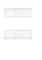
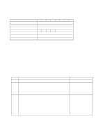
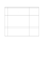
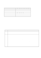
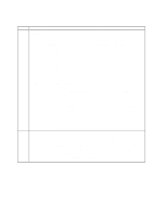
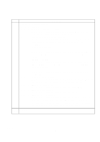
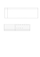
6.3.2.11.3 Device Configuration Identify [B1h, Sub 02h] Task File Registers Command Cylinder High Cylinder Low Device/Head Sector Number Sector Count Features DRV : Device selection bit 76543210 B1h XX XX - X - DRV XX XX XX 02h 0 : DRV0 1:DRV1 The DEVICE CONFIGURATION IDENTIFY command returns a 512 byte data structure via PIO data-in transfer. The content of this data structure indicates the selectable commands, modes, and feature sets that the device is capable of supporting. If a DEVICE CONFIGURATION SET command has been issued reducing the capabilities, the response to an IDENTIFY DEVICE command will reflect the reduced set of capabilities, while the DEVICE CONFIGURATION IDENTIFY command will reflect the entire set of selectable capabilities. The format of the Device Configuration Overlay data structure is shown in Table 6.18 If the device has executed a previous DEVICE CONFIGURATION FREEZE LOCK command since powerup, this device returns command aborted. Word 0 1 2 Table 6.18 Device Configuration Identify Data Structure Description Data Structure Revision Multiword DMA modes supported bit 15 - 3 0 = Reserved bit 2 1 = Multiword DMA mode 2 and below are supported bit 1 1 = Multiword DMA mode 1 and below are supported bit 0 1 = Multiword DMA mode 0 is supported Ultra DMA modes supported bit 15 - 6 0 = Reserved bit 5 1 = Ultra DMA mode 5 and below are supported bit 4 1 = Ultra DMA mode 4 and below are supported bit 3 1 = Ultra DMA mode 3 and below are supported bit 2 1 = Ultra DMA mode 2 and below are supported bit 1 1 = Ultra DMA mode 1 and below are supported bit 0 1 = Ultra DMA mode 0 is supported Value (HEX.) 0001h 0007h 003Fh K6602705 Rev.3 08.20.01 - 89 -
-
 1
1 -
2
-
3
-
4
-
5
-
6
-
7
-
8
-
9
-
10
-
11
-
12
-
13
-
14
-
15
-
16
-
17
-
18
-
19
-
20
-
21
-
22
-
23
-
24
-
25
-
26
-
27
-
28
-
29
-
30
-
31
-
32
-
33
-
34
-
35
-
36
-
37
-
38
-
39
-
40
-
41
-
42
-
43
-
44
-
45
-
46
-
47
-
48
-
49
-
50
-
51
-
52
-
53
-
54
-
55
-
56
-
57
-
58
-
59
-
60
-
61
-
62
-
63
-
64
-
65
-
66
-
67
-
68
-
69
-
70
-
71
-
72
-
73
-
74
-
75
-
76
-
77
-
78
-
79
-
80
-
81
-
82
-
83
-
 84
84 -
 85
85 -
 86
86 -
 87
87 -
 88
88 -
 89
89 -
 90
90 -
 91
91 -
 92
92 -
 93
93 -
 94
94 -
95
-
96
-
97
-
98
-
99
-
100
-
101
-
102
-
103
-
104
-
105
-
106
-
107
-
108
-
109
-
110
-
111
-
112
 |
 |
