Hitachi DK23DA-30F Owners Manual - Page 92
Device Configuration Set Command
 |
View all Hitachi DK23DA-30F manuals
Add to My Manuals
Save this manual to your list of manuals |
Page 92 highlights
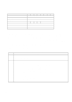
Word 2 Table 6.19 Device Configuration Set Command Data Structure (Continued) Description Ultra DMA modes supported bit 15 - 6 0 = Reserved bit 5 1 = Ultra DMA mode 5 and below are supported Bit 5 is cleared to select no support for Ultra DMA mode 5. This bit shall not be cleared if Ultra DMA mode 5 is currently selected. bit 4 1 = Ultra DMA mode 4 and below are supported Bit 4 is cleared to select no support for Ultra DMA mode 4. This bit shall not be cleared if Ultra DMA mode 5 is supported or if Ultra DMA mode 5 or 4 is selected. bit 3 1 = Ultra DMA mode 3 and below are supported Bit 3 is cleared to select no support for Ultra DMA mode 3. This bit shall not be cleared if Ultra DMA mode 5 or 4 is supported or if Ultra DMA mode 5, 4, or 3 is selected. bit 2 1 = Ultra DMA mode 2 and below are supported Bit 2 is cleared to select no support for Ultra DMA mode 2. This bit shall not be cleared if Ultra DMA mode 5, 4, or 3 is supported or if Ultra DMA mode 5, 4, 3, or 2 is selected. bit 1 1 = Ultra DMA mode 1 and below are supported Bit 1 is cleared to select no support for Ultra DMA mode 1. This bit shall not be cleared if Ultra DMA mode 5, 4, 3, or 2 is supported or if Ultra DMA mode 5, 4, 3, 2, or 1 is selected. bit 0 1 = Ultra DMA mode 0 is supported Bit 0 is cleared to select no support for Ultra DMA mode 0. This bit shall not be cleared if Ultra DMA mode 5, 4, 3, 2, or 1 is supported or if Ultra DMA mode 5, 4, 3, 2, 1, or 0 is selected. 3 - 6 Maximum LBA Address Words 3 - 6 define the maximum LBA address. This shall be the highest address accepted by the device after execution of the command. When this value is changed, the content of IDENTIFY DEVICE command are changed as described in the SET MAX ADDRESS command descriptions to reflect the maximum address set with this command. This value does not be changed and command aborted is returned if a Host Protected Area has been established by the execution of a SET MAX ADDRESS command. K6602705 Rev.3 08.20.01 - 92 -
-
 1
1 -
2
-
3
-
4
-
5
-
6
-
7
-
8
-
9
-
10
-
11
-
12
-
13
-
14
-
15
-
16
-
17
-
18
-
19
-
20
-
21
-
22
-
23
-
24
-
25
-
26
-
27
-
28
-
29
-
30
-
31
-
32
-
33
-
34
-
35
-
36
-
37
-
38
-
39
-
40
-
41
-
42
-
43
-
44
-
45
-
46
-
47
-
48
-
49
-
50
-
51
-
52
-
53
-
54
-
55
-
56
-
57
-
58
-
59
-
60
-
61
-
62
-
63
-
64
-
65
-
66
-
67
-
68
-
69
-
70
-
71
-
72
-
73
-
74
-
75
-
76
-
77
-
78
-
79
-
80
-
81
-
82
-
83
-
84
-
85
-
86
-
 87
87 -
 88
88 -
 89
89 -
 90
90 -
 91
91 -
 92
92 -
 93
93 -
 94
94 -
 95
95 -
 96
96 -
 97
97 -
98
-
99
-
100
-
101
-
102
-
103
-
104
-
105
-
106
-
107
-
108
-
109
-
110
-
111
-
112
 |
 |
