Hitachi DK23DA-30F Owners Manual - Page 96
Interface Signal Timing, 4.1 Data Transfer Timing
 |
View all Hitachi DK23DA-30F manuals
Add to My Manuals
Save this manual to your list of manuals |
Page 96 highlights
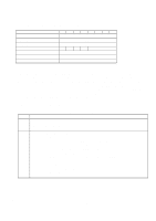
6.4 Interface Signal Timing 6.4.1 Data Transfer Timing Figures 6-4, 6-5, and 6-7 show the timing for asserting interface signals for transferring 16-bit and 8-bit data. Figure 6-4 PIO Data Transfer Timing(Mode 4) t0 Addr Valid *1 t1 t2 t9 DIOR-/DIOW- t2i t8 Write Data Valid *2 Read Data Valid *2 t7 IOCS16- t3 t4 t5 t6 t6Z *1 Device Address consists of signals CS0-, CS1-, and DA2-0 *2 Data consists of DD0-15(16 bit) or DD0-7(8 bit) SYMBOL Description MIN(ns) t0 Cycle Time 120 t1 Address Valid to DIOR-/DIOW- Setup 25 t2 DIOR-/DIOW- Pulse Width 70 t2i DIOR-/DIOW- Recovery 25 t3 DIOW- Data Setup 20 t4 DIOW- Data Hold 10 t5 DIOR- Data Setup 20 t6 DIOR- Data Hold 5 t6Z DIOR- Data tristate t7 Addr Valid To IOCS16- Assertion(MAX) t8 Addr Valid To IOCS16- Negation (MAX) t9 DIOR-/DIOW- to Address Valid Hold 10 MAX(ns) 30 40 30 K6602705 Rev.3 08.20.01 - 96 -
-
 1
1 -
2
-
3
-
4
-
5
-
6
-
7
-
8
-
9
-
10
-
11
-
12
-
13
-
14
-
15
-
16
-
17
-
18
-
19
-
20
-
21
-
22
-
23
-
24
-
25
-
26
-
27
-
28
-
29
-
30
-
31
-
32
-
33
-
34
-
35
-
36
-
37
-
38
-
39
-
40
-
41
-
42
-
43
-
44
-
45
-
46
-
47
-
48
-
49
-
50
-
51
-
52
-
53
-
54
-
55
-
56
-
57
-
58
-
59
-
60
-
61
-
62
-
63
-
64
-
65
-
66
-
67
-
68
-
69
-
70
-
71
-
72
-
73
-
74
-
75
-
76
-
77
-
78
-
79
-
80
-
81
-
82
-
83
-
84
-
85
-
86
-
87
-
88
-
89
-
90
-
 91
91 -
 92
92 -
 93
93 -
 94
94 -
 95
95 -
 96
96 -
 97
97 -
 98
98 -
 99
99 -
 100
100 -
 101
101 -
102
-
103
-
104
-
105
-
106
-
107
-
108
-
109
-
110
-
111
-
112
 |
 |
