Honeywell HW7500E Service Manual - Page 45
Alternator, NOTICE
 |
UPC - 894190002049
View all Honeywell HW7500E manuals
Add to My Manuals
Save this manual to your list of manuals |
Page 45 highlights
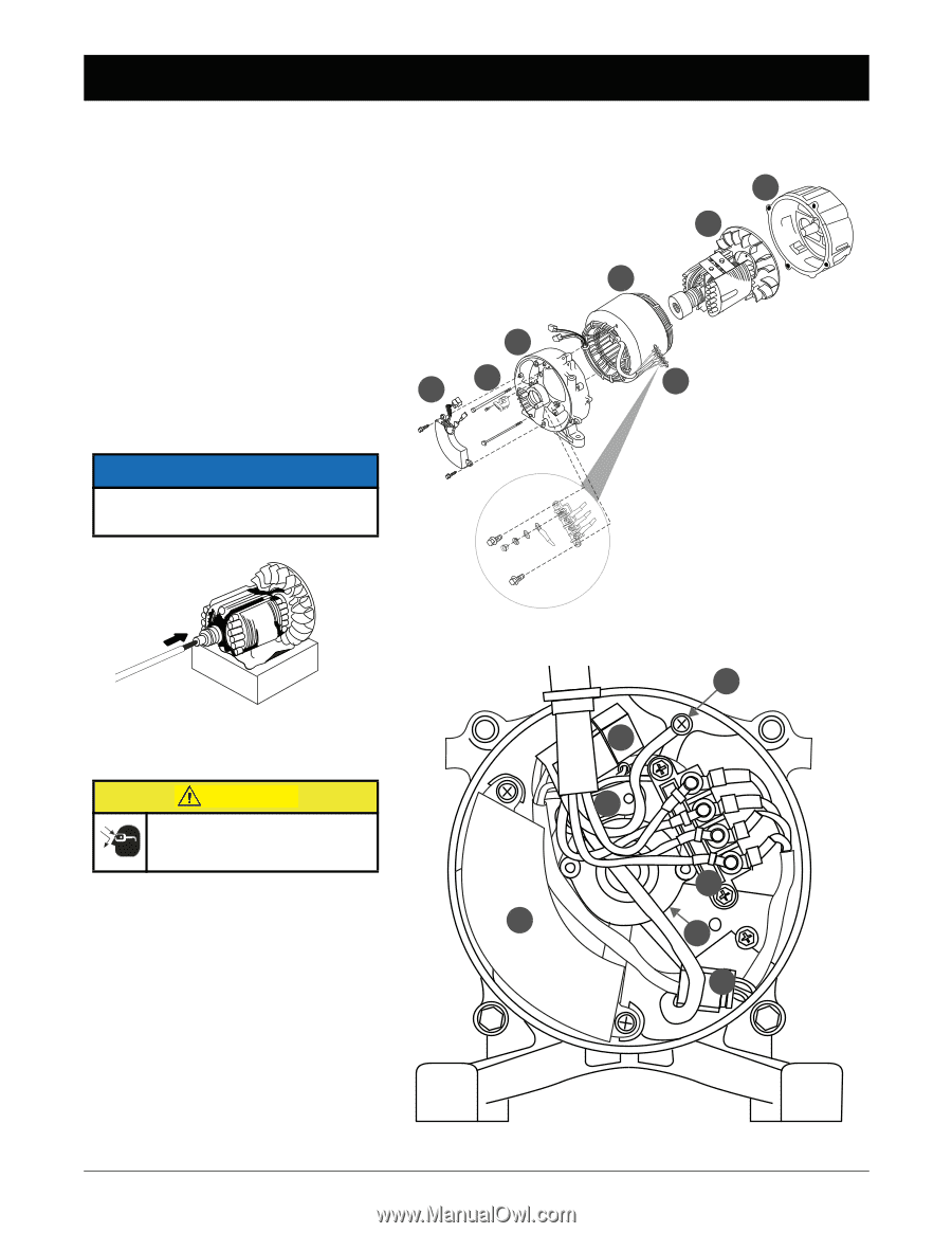
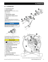
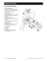
9.3 ALTERNATOR A-VOLTAGE REGULATOR B-BRUSH ASSEMBLY Before removing rotor and stator, remove brush assembly. 2 N•m (1.5 lb. ft.) C-REAR BEARING CARRIER D-MAIN WINDING TERMINAL BLOCK E-STATOR F-ROTOR Install appropriate alternator removal tool A (special tool), hold flywheel, and torque tool to 48 N•m (35 lb. ft.). NOTICE Rotor can become damaged if not properly supported. Place wooden block and rag underneath rotor for support. C B ALTERNATOR G F E D If torquing alternator removal tool does not free rotor from crankshaft, tap end of tool with brass hammer to loosen rotor. CAUTION To prevent eye injury, always wear safety glasses or goggles when using a hammer. G-ALTERNATOR ENGINE ADAPTER H-GROUND CABLE I- EXCITER WINDING CONNECTOR J-BRUSH ASSEMBLY K-TERMINAL BLOCK L-SLIP RINGS M-FUEL CUTOUT CONNECTOR N-VOLTAGE REGULATOR Also known as Automatic Voltage Regulator or AVR. Honeywell Portable Electrical Generator Service Manual H I J K N L M Alternator Illustrated Matches All Models Except HW3000 & HW3000L www.honeywellgenerators.com 9-3
-
 1
1 -
2
-
3
-
4
-
5
-
6
-
7
-
8
-
9
-
10
-
11
-
12
-
13
-
14
-
15
-
16
-
17
-
18
-
19
-
20
-
21
-
22
-
23
-
24
-
25
-
26
-
27
-
28
-
29
-
30
-
31
-
32
-
33
-
34
-
35
-
36
-
37
-
38
-
39
-
 40
40 -
 41
41 -
 42
42 -
 43
43 -
 44
44 -
 45
45 -
 46
46 -
 47
47 -
 48
48 -
 49
49 -
 50
50 -
51
-
52
-
53
-
54
-
55
-
56
 |
 |