Honeywell HW7500E Service Manual - Page 52
Fan Cover
 |
UPC - 894190002049
View all Honeywell HW7500E manuals
Add to My Manuals
Save this manual to your list of manuals |
Page 52 highlights
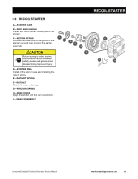
FAN COVER 9.10 FAN COVER A-COOLING FAN Install by aligning the three lugs on the rear side of the fan with the small hole in the flywheel. When disassembling and assembling, take care not to damage the fan blades. B-STARTER PULLEY Install by aligning the hole in the pulley with the lug on the cooling fan. C-FLANGE NUT Hold the flywheel by placing a screwdriver into the pulley. 105 N•m (77 lb. ft.) D-FAN COVER Remove and install with the recoil starter assembly. E-RECOIL STARTER ASSEMBLY Install with the recoil starter handle position as shown. A B C D E 9-10 www.honeywellgenerators.com Honeywell Portable Electrical Generator Service Manual
-
 1
1 -
2
-
3
-
4
-
5
-
6
-
7
-
8
-
9
-
10
-
11
-
12
-
13
-
14
-
15
-
16
-
17
-
18
-
19
-
20
-
21
-
22
-
23
-
24
-
25
-
26
-
27
-
28
-
29
-
30
-
31
-
32
-
33
-
34
-
35
-
36
-
37
-
38
-
39
-
40
-
41
-
42
-
43
-
44
-
45
-
46
-
 47
47 -
 48
48 -
 49
49 -
 50
50 -
 51
51 -
 52
52 -
 53
53 -
 54
54 -
 55
55 -
 56
56
 |
 |

FAN COVER
9-10
www.honeywellgenerators.com
Honeywell Portable Electrical Generator Service Manual
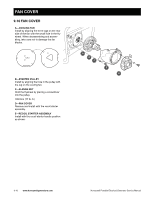
9.10 FAN COVER
A—COOLING FAN
Install by aligning the three lugs on the rear
side of the fan with the small hole in the fly-
wheel. When disassembling and assem-
bling, take care not to damage the fan
blades.
B—STARTER PULLEY
Install by aligning the hole in the pulley with
the lug on the cooling fan.
C—FLANGE NUT
Hold the flywheel by placing a screwdriver
into the pulley.
105 N•m (77 lb. ft.)
D—FAN COVER
Remove and install with the recoil starter
assembly.
E—RECOIL STARTER ASSEMBLY
Install with the recoil starter handle position
as shown.
B
C
D
A
E