Honeywell HW7500E Service Manual - Page 55
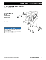
INDEX, Wheel, Leg, & Handle Assembly - generator parts
 |
UPC - 894190002049
View all Honeywell HW7500E manuals
Add to My Manuals
Save this manual to your list of manuals |
Page 55 highlights
10: INDEX A Air Filter Maintenance 7-3 Alternator 9-2, 9-3 Automatic Voltage Regulator (AVR) 8-5, 8-9, 9-3 B Battery 4-1, 7-8 Breakers 4-1 C Components breakers 4-1 choke control 4-1 engine control switch 4-1 fuel shut-off valve 4-1 recoil starter handle 4-1 spark plug cap 4-1 Control Panel 9-1 E Electrical Diagnostics 8-2 all other models 8-6, 9-12 HW3000/L models 8-2 Engine 7-3, 9-2 Engine Control Switch 4-1, 9-1 Engine Diagnostics 8-10 Evaporative Emissions Control System 9-5 F Fuel Gage 4-1, 9-4 Fuel Recommendations 7-2 Fuel Sediment Cup 7-5, 9-4 Fuel Shut-off Valve 4-1, 9-4 Fuel Strainer 9-4 Fuel Tank 9-4, 9-5 Fuel, Oxygenated 7-2 G Governor 7-7 Ground Terminal 4-1 M Maintenance 7-1 air filter 7-3 battery service 7-8 fuel sediment cup 7-5 governor adjustment 7-7 governor range adjustment 7-7 schedule 7-1 spark arrestor screen 7-6 spark plug 7-5 valve lash 7-7 Muffler 4-1, 9-6 O Oil Fill Dipstick 4-1 Oil Recommendations 7-3 Outlets 4-1, 9-1 P Power Control Center 4-1, 9-1 breakers 4-1, 9-1 electrical outlets 4-1, 9-1 ground terminal 4-1 R Rotor 9-2, 9-3 S Safety, Important Instructions 1-1 Service and Disassembly 9-1 alternator 9-3 carburetor 9-7 control panel 9-1 engine and alternator 9-2 evaporative emissions control system 9-5 fan cover 9-10 fuel tank system 9-4 muffler 9-6 preparing for 5-1 recoil starter 9-9 starting system 9-8 wheel, leg, & handle assembly 9-11 Service Repair Time 6-1 Spark Arrestor 4-1, 7-6, 9-6 Spark Plug 4-1, 7-5 Specifications 3-1 T Tools, Service 5-1 Torque Information 3-2 Transporting Generator 5-1 Troubleshooting 8-1 V Valve Lash 7-7 Voltage Regulator 8-5, 8-9, 9-3 W Warranty emissions control 2-2 limited 2-1 replacement parts 2-4 Wheel, Leg, & Handle Assembly 9-11 Wiring Diagrams 3-3 Honeywell Portable Electrical Generator Service Manual www.honeywellgenerators.com 10-1
-
 1
1 -
2
-
3
-
4
-
5
-
6
-
7
-
8
-
9
-
10
-
11
-
12
-
13
-
14
-
15
-
16
-
17
-
18
-
19
-
20
-
21
-
22
-
23
-
24
-
25
-
26
-
27
-
28
-
29
-
30
-
31
-
32
-
33
-
34
-
35
-
36
-
37
-
38
-
39
-
40
-
41
-
42
-
43
-
44
-
45
-
46
-
47
-
48
-
49
-
 50
50 -
 51
51 -
 52
52 -
 53
53 -
 54
54 -
 55
55 -
 56
56
 |
 |
