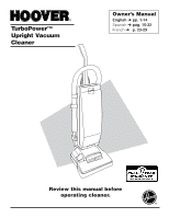
Hoover U5415-900 Owners Manual - Page 4
Handle assembly
 |
View all Hoover U5415-900 manuals
Add to My Manuals
Save this manual to your list of manuals |
Page 4 highlights
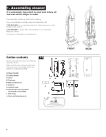
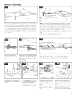
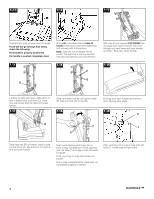
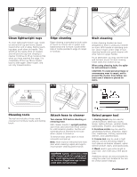
FRONT UP FRONT Handle assembly 1-2 C 1-3 F G D B A Place upper (A) and lower (B) handle sections on a flat surface with cord hooks (C) on top. With hands on sides of handle sections, push sections together firmly until they "click" into place. *Do not press against the rod (D) extending from the lower handle. If the rod breaks or bends, the cleaner will not work properly. Do not push handle together with your hands on the ends of the sections. E D Note: The small red tab (E) above the ON/OFF switch is for shipping purposes only and may fall off during assembly. If it does not fall off, the tab will be removed during the final steps of assembly. Turn handle over. Insert large rectangular end of cord (F) into pocket in bottom of handle, with side marked "UP" visible. Make sure rectangular end is pushed into the handle as far as possible. Slide cord protector (G) toward upper handle. 1-4 1-5 1-6 H UP I Rotate cord protector on cord until you see its arrow (H). With arrow on cord protector pointing toward arrow on upper handle, press groove (I) in cord protector into slot in upper handle. Pull cord tight. 1-7 1-8 K J Press cord into place at each of the three notches indicated. Do not plug cleaner in until assembly is totally complete. 1-9 1-10 N K M L J Note location of tapered rails (J) on bracket (K) and on lower handle. With printed side of bracket (K) facing up, slide rails on bracket onto rails (J) on lower handle until bracket snaps past the lock tab (L). Pull bracket toward bottom of handle slightly to make sure bracket is locked in place. Make sure hole in bracket aligns with hole in handle (M). With cord hooks to the back, place assembled handle onto handle base of cleaner body (N). Rock handle side to side while pushing down firmly. Extra pushing effort may be required. 4
-
 1
1 -
 2
2 -
 3
3 -
 4
4 -
 5
5 -
 6
6 -
 7
7 -
 8
8 -
 9
9 -
 10
10 -
11
-
12
-
13
-
14
-
15
 |
 |
