Hotpoint RGA724EKWH Installation Instructions - Page 29
Caution, Seal The Openings, Light The Pilots - pilot light
 |
UPC - 084691131717
View all Hotpoint RGA724EKWH manuals
Add to My Manuals
Save this manual to your list of manuals |
Page 29 highlights
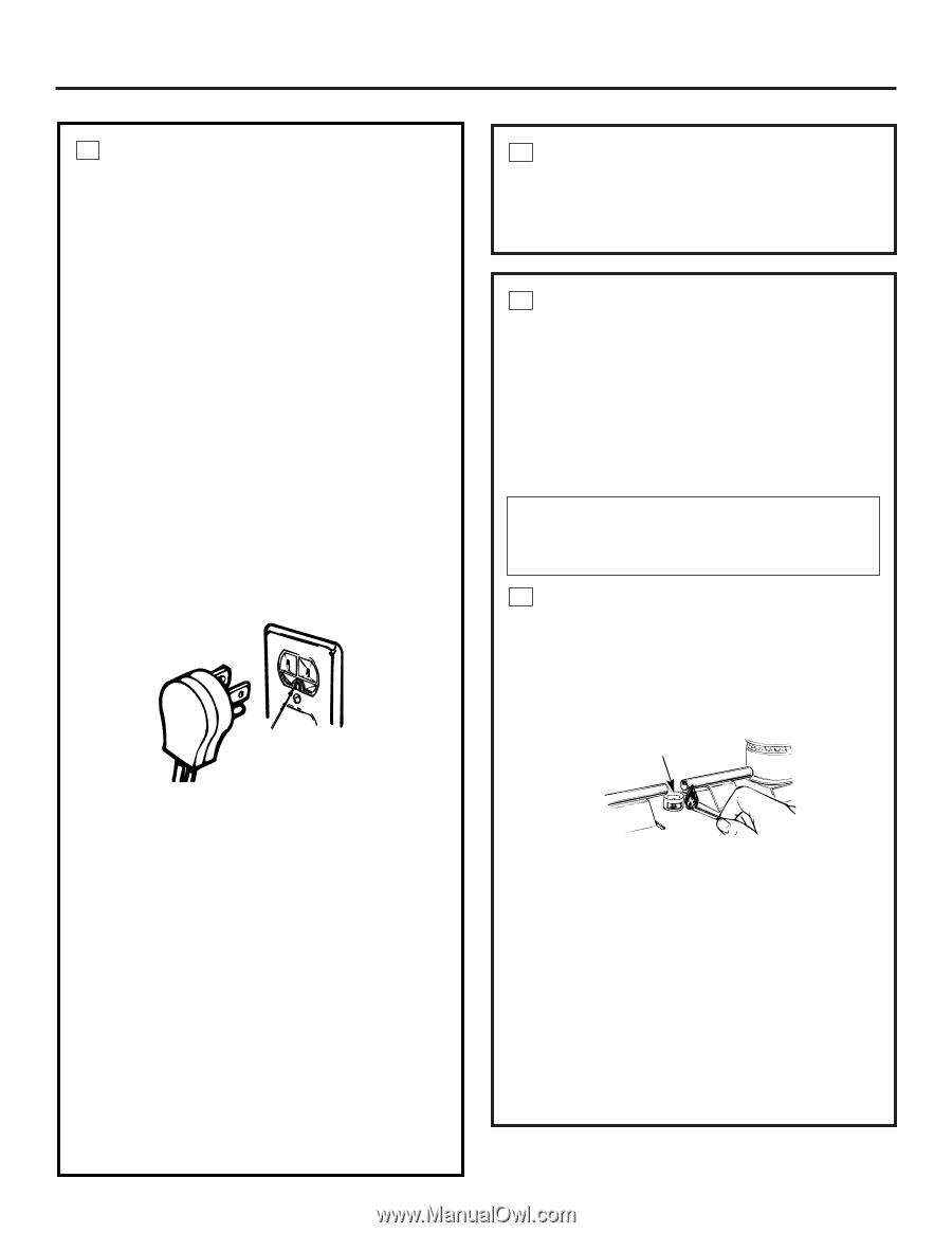
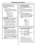
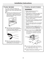
Installation Instructions 3 ELECTRICAL CONNECTIONS (on electric ignition models) Electrical Requirements 120-volt, 60 Hertz, properly grounded dedicated circuit protected by a 15-amp or 20-amp circuit breaker or time delay fuse. Extension Cord Cautions Because of potential safety hazards associated with certain conditions, we strongly recommend against the use of an extension cord. However, if you still elect to use an extension cord, it is absolutely necessary that it be a UL-listed, 3-wire grounding-type appliance extension cord and that the current carrying rating of the cord in amperes be equivalent to, or greater than, the branch circuit rating. Grounding IMPORTANT-(Please read carefully) FOR PERSONAL SAFETY, THIS APPLIANCE MUST BE PROPERLY GROUNDED. Preferred Method Ensure proper ground exists before use 4 SEAL THE OPENINGS Seal any openings in the wall behind the range and in the floor under the range when hookups are completed. 5 LIGHT THE PILOTS (For models equipped with standing pilots. If the range is an electric ignition model, the burners are ignited by electric ignition which eliminates the need for standing pilot lights.) The range should be installed in its permanent position before any pilots are lit or adjusted. CAUTION - Make sure the surface burner control knobs are in the OFF position before attempting to light the pilots. A Light the Surface Burner Pilots 1. Lift the cooktop up and prop it open with the prop rod provided (see the Care and cleaning of the range section). 2. Locate the 2 pilot ports and light each of them with a match. Pilot port The power cord of this appliance is equipped with a 3-prong (grounding) plug which mates with a standard 3-prong grounding wall receptacle to minimize the possibility of electric shock hazard from this appliance. The customer should have the wall receptacle and circuit checked by a qualified electrician to make sure the receptacle is properly grounded. Where a standard 2-prong wall receptacle is encountered, it is the personal responsibility and obligation of the customer to have it replaced with a properly grounded 3-prong wall receptacle. DO NOT, UNDER ANY CIRCUMSTANCES, CUT OR REMOVE THE THIRD (GROUND) PRONG FROM THE POWER CORD. 3. To avoid pilot outage, use caution when closing cooktop after lighting pilots. NOTE: Do not leave standing pilot lit in a newly constructed or remodeled home or apartment that will be unoccupied for more than a month. Each pilot flame was adjusted at the factory to be approximately 5/16″ tall. A tinge of yellow appearing at the upper tip is normal. If you find pilot adjustment is necessary, follow instructions in Step B. 29
-
 1
1 -
2
-
3
-
4
-
5
-
6
-
7
-
8
-
9
-
10
-
11
-
12
-
13
-
14
-
15
-
16
-
17
-
18
-
19
-
20
-
21
-
22
-
23
-
 24
24 -
 25
25 -
 26
26 -
 27
27 -
 28
28 -
 29
29 -
 30
30 -
 31
31 -
 32
32 -
 33
33 -
 34
34 -
35
-
36
 |
 |