Hunter 40170 Owner's Manual - Page 32
Wiring Diagrams, Cont.
 |
View all Hunter 40170 manuals
Add to My Manuals
Save this manual to your list of manuals |
Page 32 highlights
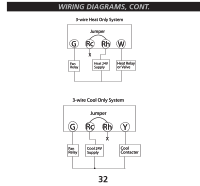
wiring diagrams, cont. 3-wire Heat Only System Jumper G Rc Rh W Fan Relay X Heat 24V Supply Heat Relay or Valve 3-wire Cool Only System Jumper G Rc Rh Y Fan Relay X Cool 24V Supply Cool Contacter 32
-
 1
1 -
2
-
3
-
4
-
5
-
6
-
7
-
8
-
9
-
10
-
11
-
12
-
13
-
14
-
15
-
16
-
17
-
18
-
19
-
20
-
21
-
22
-
23
-
24
-
25
-
26
-
 27
27 -
 28
28 -
 29
29 -
 30
30 -
 31
31 -
 32
32 -
 33
33
 |
 |

±2
G
Rc
Rh
W
Heat 24V
Supply
Heat Relay
or Valve
X
Jumper
3-wire Heat Only System
Fan
Relay
G
Rc
Rh
W
Heat 24V
Supply
Heat Relay
or Valve
X
Jumper
3-wire Heat Only System
Fan
Relay
G
Rc
Rh
Y
Cool
Contacter
Cool 24V
Supply
X
Jumper
3-wire Cool Only System
Fan
Relay
G
Rc
Rh
Y
Cool
Contacter
Cool 24V
Supply
X
Jumper
3-wire Cool Only System
Fan
Relay
WIRING DIAGRAMS, CONT.