Icom IC-718 Instruction Manual
Icom IC-718 Manual
 |
View all Icom IC-718 manuals
Add to My Manuals
Save this manual to your list of manuals |
Icom IC-718 manual content summary:
- Icom IC-718 | Instruction Manual - Page 1
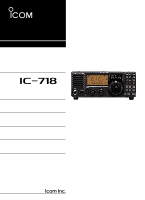
INSTRUCTION MANUAL HF ALL BAND TRANSCEIVER i718 This device complies with Part 15 of the FCC rules. Operation is subject to the following two conditions: (1) This device may not cause harmful - Icom IC-718 | Instruction Manual - Page 2
, set the transceiver's RF output power to less than the linear amplifier's maximum input level, otherwise, the linear amplifier will be damaged. Use Icom microphones only (supplied or optional). Other manufacturer's microphones have different pin assignments, and connection to the IC-718 may damage - Icom IC-718 | Instruction Manual - Page 3
CPU 53 11 SPECIFICATIONS 54 12 OPTIONS 55 - 56 13 CONTROL COMMAND 57 - 58 s Remote jack (CI-V) information 57 14 INTERNAL VIEWS 59 s Top view 59 s Bottom view 59 SUPPLIED ACCESSORIES q w The transceiver comes with the following accessories. Qty. q DC power cable 1 w Hand microphone (HM - Icom IC-718 | Instruction Manual - Page 4
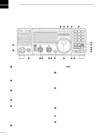
2 PANEL DESCRIPTION s Front panel Speaker - Icom IC-718 | Instruction Manual - Page 5
) ➥ Push momentarily to toggle between the pre-programmed normal, wide and narrow IF filters for the selected operating mode. @1 MODE SWITCHES [LSB/USB]/[CW/CW- R]/[RTTY/RTTY-R]/[AM] (p. 20) Push to toggle an operating mode. • Push[MODE] for 1 sec. during SSB mode to toggle be- tween LSB or USB - Icom IC-718 | Instruction Manual - Page 6
Automatic Notch Filter function ON or OFF. Functions in SSB and AM modes. • An optional UT-106 DSP UNIT is required programmed scan in VFO mode. ➥ Push momentarily to start/stop the memory scan in memory mode. @9 VOX SWITCH/9 [VOX•9] (p. 27) ➥ Turn the VOX function ON or OFF when pushed in SSB modes - Icom IC-718 | Instruction Manual - Page 7
in SSB mode. ➥ "SCAN" appears when the scan function is activated. • Flashes when scan is paused. y DSP UNIT INDICATOR (p. 49) Appears when an optional UT-106 DSP UNIT is installed. u AUTOMATIC NOTCH FILTER INDICATOR (p. 23) Appears when the optional Automatic Notch Filter function is in use - Icom IC-718 | Instruction Manual - Page 8
a straight key Rear panel view e TUNER CONTROL SOCKET [TUNER] (p. 14) Accepts the control cable from an optional AH-4 AUTOMATIC ANTENNA TUNER. r CI-V REMOTE CONTROL JACK [REMOTE] (p. 57) Designed for use with a personal computer for remote operation of transceiver functions. t EXTERNAL SPEAKER JACK - Icom IC-718 | Instruction Manual - Page 9
. When grounded, transmits. 13 9 10 11 12 5678 1234 Rear panel view 4 BDT Data line for the optional AT-180. 5 BAND Band voltage output. (Varies with amateur band) 6 ALC ALC voltage input. 7 NC 8 13.8 V 13.8 V output when power is ON. SPECIFICATIONS COLOR Output voltage Output current - Icom IC-718 | Instruction Manual - Page 10
CW PADDL in initial set mode. (p. 31) w PTT SWITCH Push and hold to transmit; release to receive. • MICROPHONE CONNECTOR (Front view) q Microphone can damage the internal 8 V regulator. • HM-36 SCHEMATIC DIAGRAM MICROPHONE MICROPHONE CABLE MICROPHONE PLUG MIC ELEMENT + 10µ 2k 4700p + 0.33µ - Icom IC-718 | Instruction Manual - Page 11
. 2.0:1, the transceiver's power drops to protect the final transistor. In this case, an antenna tuner is useful to match the transceiver and antenna. Low SWR allows full power for transmitting even when using the antenna tuner. The IC-718 has an SWR meter to monitor the antenna SWR continuously - Icom IC-718 | Instruction Manual - Page 12
3 INSTALLATION AND CONNECTIONS s Required connections • Front panel MICROPHONES (p. 55) HM-36 SM-20 - Icom IC-718 | Instruction Manual - Page 13
ATT TUNER ∫ CH DN UP ∫ HEADPHONES • Rear panel AH-4 (p. 55) with AH-2b or long wire ANTENNA (p. 13) Connects a liner amprifier, etc. [REMOTE] (p. 57) Used for computer control and transceive operation. ACC SOCKETS (p. 7) [SEND], [ALC] (p. 14) Used for connecting a non-Icom linear amplifier - Icom IC-718 | Instruction Manual - Page 14
3 INSTALLATION AND CONNECTIONS s Power supply connections Use an optional PS-85 DC POWER SUPPLY when operating the IC-718 with AC power. Refer to the diagrams below. CONNECTING PS-85 DC POWER SUPPLY CAUTION: Before connecting the DC power cable, check the following important items. Make sure: • - Icom IC-718 | Instruction Manual - Page 15
10 11 12 5678 1234 IC-718 CONNECTING THE IC-4KL Coaxial cable (supplied with the IC-4KL) ACC cable (supplied with the IC-4KL) OPC599 conversion cable (option) To an antenna ACC ANT ACC 13 9 10 11 12 5678 1234 IC-718 IC-4KL Remote controller Ground IC-4KL Remote control cable (supplied with - Icom IC-718 | Instruction Manual - Page 16
IC-718 SEND 13 9 10 11 12 5678 1234 ALC The specifications for the SEND relay are 16 V DC 2 A. If this level is exceeded, a large external relay must be used. s External antenna tuners CONNECTING THE AH-4 (p. 29) Long wire or optional AH-2b Coaxial cable (from the AH-4) Control cable IC-718 - Icom IC-718 | Instruction Manual - Page 17
by referring to Chapter 3. Then, reset the transceiver using the following procedure. Resetting CLEARS all programmed contents in memory channels and returns programmed values in quick/initial set mode to default values. q Make sure the transceiver power is OFF. w While pushing and holding [∫ UP - Icom IC-718 | Instruction Manual - Page 18
change the frequency with the tuning dial and select the operating mode with the [MODE] switch or call up previously accessed frequency and modes with the band stacking register (p. 18). The IC-718 has two VFOs, specially suited for split frequency opration. The VFOs are called VFO A and VFO B. You - Icom IC-718 | Instruction Manual - Page 19
times to select the desired ham band. • For general coverage receiver use The IC-718 has a general coverage receiver band. q Push [∫ UP] or [√ DN] one or more times to select the general coverage receiver band. w Select the desired operating mode with the mode switch. (p. 20). e Rotate the tuning - Icom IC-718 | Instruction Manual - Page 20
15.10000 MHz BAND CW LSB LSB CW USB USB BAND 18 MHz 21 MHz 24 MHz 28 MHz 29 MHz BAND 18.10000 MHz 21.20000 MHz 24.95000 MHz 28.50000 MHz 29.50000 MHz BAND USB USB USB USB USB D Band selection All HF ham bands and a general coverage receiver band are included in the IC-718. Push [∫ UP]/[√ DN - Icom IC-718 | Instruction Manual - Page 21
[LOCK] momentarily to toggle the lock function ON and OFF. • "LOCK" appears in the function display while the lock function is activated. Selectable for each mode. "LOCK" appears while the lock function is activated. 19 - Icom IC-718 | Instruction Manual - Page 22
(p. 44). • [RF/SQL] control priority Set mode setting USB, LSB, CW, RTTY rS (RF/SQL) (default) RF/SQL At (AUTO) RF GAIN AM RF/SQL SQL* Sq (SQL) SQL* SQL* * The RF gain is set to maximum level when the [RF/SQL] is set as [SQL] control. The RF (Radio Frequency) gain is used to adjust the - Icom IC-718 | Instruction Manual - Page 23
the IF frequency up to ±1.2 KHz in SSB/CW/RTTY modes and up ±250 Hz in CW-narrow/RTTY narrow modes. The IF shift is not available in AM mode. IF SHIFT OPERATION EXAMPLE • Adjust the [SHIFT] control for a minimum interference signal level. • When IF shift is used, the audio tone may be changed - Icom IC-718 | Instruction Manual - Page 24
• [NB] indicator disappears. • When using the noise blanker, received signals may be distorted if they are excessively strong. • The noise blanker function in AM mode can be deactivated depending on initial set mode setting. (p. 45) ï Peak meter hold The peak meter hold function freezes the highest - Icom IC-718 | Instruction Manual - Page 25
Noise reduction activated Desired signal (CW) q Push [NR] to turn The noise reduction function is available in all modes. w Push [NR] for 1 sec. Filter) function When an optional UT-106 is installed (DSP appears in the function display), an auto notch function can be used. Auto notch OFF Auto - Icom IC-718 | Instruction Manual - Page 26
Name FL-52A FL-53A FL-96 FL-222 FL-257 Band width 500 Hz/-6dB 250 Hz/-6dB 2.8 KHz/-6dB 1.8 KHz/-6dB 3.3 KHz/-6dB Mode CW/RTTY-N CW/RTTY-N SSB-W SSB-N SSB-W When an optional filter is installed, set the optional filter in initial set mode. An optional filter is not selected by default. • Filter - Icom IC-718 | Instruction Manual - Page 27
•The filter combinations are stored depending on operating modes. i Push [POWER] to exit initial set mode. • Wide filter setting table SSB CW RTTY AM no no THU (6 K) no THU (6 K) no THU (6 K) - - - FL-52A no THU (6 K) no THU (6 K) no THU (6 K) - - - • Narrow filter setting table no FL-52A SSB - Icom IC-718 | Instruction Manual - Page 28
is continuously selectable. • Available power SSB/CW/RTTY: 2 (or less) -100 W AM: 2 (or less) -40 W* *Carrier power • Setting microphone gain Microphone gain must be adjusted properly so that your signal does not distort when transmitted. q Select SSB or another phone mode. w Push [SET] for - Icom IC-718 | Instruction Manual - Page 29
5 RECEIVE AND TRANSMIT ˛ ˛ ï Microphone compressor IC-718 has a built-in, low distortion Mic compressor circuit. This circuit increases your average talk power in SSB mode and is especially useful for DX'ing when the receiving station is having difficulty copying your signal. q Selecting USB or LSB - Icom IC-718 | Instruction Manual - Page 30
u Push [PWR] to turn power ON again. • AUTO TUNE: Push [TUNER] to turn the tuner ON. The antenna is tuned automatically during transmission when the an- tenna SWR is higher than 1.5:1. • When the tuner is OFF, " " goes out. • MANUAL TUNING During SSB operation on HF bands at low voice levels - Icom IC-718 | Instruction Manual - Page 31
TRANSMIT ï Optional AH-4 AUTOMATIC ANTENNA TUNER operation The AH-4 matches the IC-718 to a long wire antenna more than 7 m/23 ft long (3.5 MHz and above). • See p. 14 for connection. • See the AH-4 instruction manual for AH-4 installa- tion and antenna connection details. TUNER OPERATION Tuning - Icom IC-718 | Instruction Manual - Page 32
The IC-718 has a built-in circuit of measuring antenna SWR-no external equipment or special adjustments are necessary. ï Measuring SWR q Confirm that the output power is over 30 W. w Push [SET] one or more times to select the SWR meter. e Push [MODE] one or more times to select CW or RTTY operation - Icom IC-718 | Instruction Manual - Page 33
such as a foot switch; or use the RTTY 13 9 10 11 12 5678 SEND terminal for all bands. (See p. 33) 1234 ˛ ˛ See p. 32 for connection details: Paddle operation from front panel MIC connector. [MICROPHONE] 5 RECEIVE AND TRANSMIT Paddle Straight key Initial set mode setting (p. 45) : normal - Icom IC-718 | Instruction Manual - Page 34
CW and CW-R modes. ï Electronic CW keyer The IC-718 has an electronic keyer. Both keying speed and weight (the ratio of dot : space : dash) can be set in quick set mode. • Setting the electronic keyer q Push [MODE] one or more times to select CW mode. w While pushing and holding [SET], push [POWER - Icom IC-718 | Instruction Manual - Page 35
RTTY ï Connection for RTTY(FSK) 5 RECEIVE AND TRANSMIT [ACC] [EXT SP] Rear panel TU or TNC 2-conductor 1/8˝ plug Personal computer Rear panel view 13 9 10 11 12 5678 12 34 AF GND SQL*1 AF out SEND GND FSKK Use and personal computer. Use either the ACC or microphone connector. 13 9 10 11 12 - Icom IC-718 | Instruction Manual - Page 36
select RTTY-R (RTTY reverse) mode. • Push [MODE] for 1 sec. to select RTTY-R (RTTY reverse) mode. Normal space mark 170 2125 Hz Hz BFO displayed freq. ï RTTY (AFSK) operation q Connect a terminal unit as p. 33. w Select SSB (LSB) mode with [MODE]. • Generally, LSB is used on the HF bands. e Select - Icom IC-718 | Instruction Manual - Page 37
s Memory channels The transceiver has 101 memory channels. The memory mode is very useful for quickly changing to oftenused frequencies. All 101 memory channels are tuneable which means the programmed frequency can be tuned temporarily with the tuning dial, etc. in memory mode. MEMORY CHANNEL - Icom IC-718 | Instruction Manual - Page 38
, use direct frequency entry with the keypad in advance. e Push [MW] for 1 sec. to program the displayed frequency and operating mode into the memory channel. • Preamp setting, attenuator on/off,and AGC setting can also be programmed into a memory channel. [EXAMPLE]: Programming 21.280 MHz/CW into - Icom IC-718 | Instruction Manual - Page 39
in VFO mode This is useful for transferring programmed contents to VFO. q Select VFO mode with [V/M]. mode. Frequency transferring can be performed in either VFO mode or memory mode. TRANSFERRING EXAMPLE IN VFO MODE Operating frequency : 21.320 MHz/USB (VFO) Contents of M-ch 12 : 14.180 MHz/CW - Icom IC-718 | Instruction Manual - Page 40
D Transferring in memory mode This is useful for transferring frequency and operating mode while operating in memory mode. When you have changed the frequency or operating mode in the selected memory channel: • Displayed frequency and mode are transferred. • Programmed frequency and mode in the mem - Icom IC-718 | Instruction Manual - Page 41
99 BLANK Mch 7 Mch 5 Mch 6 This scan operates in memory mode. s Preparation • Channels For programmed scan/auto memory write scan: Program scan edge frequencies into scan edge memory channels P1 and P2. For memory scan: Program 2 or more memory channels except scan edge memory channels. • Scan - Icom IC-718 | Instruction Manual - Page 42
7 SCANS s Programmed scan operation q Select VFO mode with [V/M]. w Select the desired operating mode. • The operating mode can also be changed while scanning. e Set [RF/SQL] open or closed. • See previous page for scan condition. • If the [RF/SQL] control function is set as RF control, the squelch - Icom IC-718 | Instruction Manual - Page 43
8 SET MODE s General Set mode is used for programming infrequently changed values or conditions of functions. The IC-718 has 2 separate set modes: quick set mode and initial set mode. D Quick set mode operation q While power is ON, push [SET] for 1 sec. • Quick set mode is selected and one of its - Icom IC-718 | Instruction Manual - Page 44
power). Note that while adjusting the output power, the power meter is displayed automatically. • Mic gain This item adjusts microphone sec. units. The default CW operation. There are three selectable values: oFF: No break-in operation available (default). SE : Semi break-in operation available. FL - Icom IC-718 | Instruction Manual - Page 45
, 52, 54, 56, 57, 59 can not be selected. • Key ratio This item sets the CW key ratio (or weight). The ratio can be selected from 2.8 to 4.5. The default is 30 (3.0). • RTTY mark tone This item selects RTTY tone. There are 3 selectable values: 1275, 1615 and 2125 Hz. The default is 2125 Hz - Icom IC-718 | Instruction Manual - Page 46
rotate the main dial to set on or off. • RF/SQL VR The [RF/SQL] control can be set as the RF/squelch control or automatic (acts as squelch in AM modes; as RF in SSB/CW/RTTY modes) or the squelch control. (See p. 20) The default is rS (RF/squelch). • Beep A beep sounds each time a switch is - Icom IC-718 | Instruction Manual - Page 47
the CW paddle type. Four selections are available. • n : normal (for electronic keyer use) • r : reverse (for electronic keyer use) • oF : Turns OFF the electronic keyer (for straight key use) • ud : For using the microphone's [UP]/[DN] keys insted of the paddle. The default is n (normal). SET MODE - Icom IC-718 | Instruction Manual - Page 48
oF (OFF). • PTT tune When an optional AH-4 or AT-180 AUTOMATIC ANTENNA TUNER is connected, tuning can be started automatically at the moment the PTT is pushed. The default is oF (OFF). • Speech language When an optional UT-102 VOICE SYNTHESIZER UNIT is installed, you can select between English and - Icom IC-718 | Instruction Manual - Page 49
• CI-V 731 mode When connecting the IC-718 to the IC-735 for transceive operation, you must change the operating frequency data to 4 bytes. • This item MUST be set to "on" when operating transceiver with the IC-735. The default is oF (off). • OPTION Filter When an optional IF filer is installed, this - Icom IC-718 | Instruction Manual - Page 50
the case and cover opening procedures shown here when you want to install an optional unit or adjust an internal unit, etc. CAUTION: DISCONNECT the DC power cable from the IC-718 before performing any work on the transceiver. Otherwise, there is danger of electric shock and/or equipment damage - Icom IC-718 | Instruction Manual - Page 51
P4 from J201 (MAIN unit) and P2 from J401 (MAIN unit), then remove the PLL unit. r Remove the supplied internal crystal and replace with the CR-338. t Return the PLL unit, plugs and flat cables to their original positions. y Adjust the reference frequency at C16 using a frequency counter if desired - Icom IC-718 | Instruction Manual - Page 52
case J 2603 • Turn the unit over J 2602 MAIN unit Fig. 1 UT-106 J 2602 Fig. 2 insulating case " Flat cable* Surplus cable J 2602 Rear panel UT-106 J 2603 Main unit * Supplied with UT-106 s Optional IF filters Several IF filters are available for the IC-718. You can install 1 filter for 455 KHz - Icom IC-718 | Instruction Manual - Page 53
9 INSTALLATION AND CONNECTIONS s AT-180 internal switch description The optional AT-180 has 3 operating conditions for HF band operation. Select a suitable condition according to your antenna system. ➀ Remove the top cover of the AT-180. ➁ Set the tuner switches to the desired positions according - Icom IC-718 | Instruction Manual - Page 54
the cause of a problem or solve it through the use of this chart, contact your nearest Icom Dealer or Service Center. POWER PROBLEM POSSIBLE CAUSE Power does not come on • DC power cable is improperly connected. when the [POWER] switch • Fuse is blown. is pushed. • Power Supply not turned ON - Icom IC-718 | Instruction Manual - Page 55
, try to find the source of the problem, and replace the damaged fuse with a new, rated fuse. CAUTION: DISCONNECT the DC power cable from the transceiver when changing a fuse. The IC-718 has 2 types of fuses installed for transceiver protection. • DC power cable fuses FGB 20 A • Circuitry fuse FGB - Icom IC-718 | Instruction Manual - Page 56
sideband : More than 50 dB • Microphone connector : 8-pin connector (600 Ω) • Key connector : 3-conductor 6.5 (d) mm (1⁄4˝) • SEND/ALC connector : Phono (RCA) D Receiver • Receive system : Double-conversion superheterodyne system • Sensitivity SSB, CW, RTTY AM : 0.16 µV (1.8-29.999999 MHz - Icom IC-718 | Instruction Manual - Page 57
OPTIONS IC-PW1 HF + 50 MHz 1 KW LINER AMPLIFIER Full-duty 1 kW linear amplifier including an automatic antenna tuner. Has automatic tuning and band selection capability. Full break-in (QSK) operation is possible. The amplifier/power supply unit and the remote control unit are separated. AT-180 HF - Icom IC-718 | Instruction Manual - Page 58
Transceiver mounting bracket for mobile operation. For remote receiver control using a personal computer. You can change frequencies, operating mode, memory channels, etc. Covers from 1.9-30 MHz bands. Has an SO-239 connector. 30 m (98.4 ft) coaxial cable with PL-259 connector is supplied. OPC - Icom IC-718 | Instruction Manual - Page 59
mode. • Data format The CI-V system can be operated using the following data formats. Data formats differ according to command numbers. A data area or sub command is added for some commands. IC-718 ˛ ˛ BC-25 (optional) 9-15 V DC ct- 17 personal computer mini-plug cable CONTROLLER TO IC-718 - Icom IC-718 | Instruction Manual - Page 60
stop Prog/Memo Scan Start Resume OFF Resume ON SPLIT OFF SPLIT ON Set TS ATT AF Gain RF Gain SQL Level NR Level CW Pitch RF Power MIC Gain KEY Speed BK-IN Delay Read SQL Open/Close Read SIG (S-meter) level PRE-AMP NB NR Auto Notch COMP VOX BK-IN Read ID 58 - Icom IC-718 | Instruction Manual - Page 61
and adjusted at the factory before being shipped. The transceiver warranty does not cover any problems caused by unauthorized internal adjustment. FILTER unit Carrier suppression adj. (R 2303) IC APC adj. (R 1720) Tx power adj. (R 1707) AM Tx carrier adj. (R 1730) Optional IF filter (See p. 24) 59 - Icom IC-718 | Instruction Manual - Page 62
Count on us! A-5649D-1EX-w Printed in Japan © 2000 Icom Inc. 6-9-16 Kamihigashi, Hirano-ku, Osaka 547-0002 Japan
-
 1
1 -
 2
2 -
 3
3 -
 4
4 -
 5
5 -
 6
6 -
 7
7 -
8
-
9
-
10
-
11
-
12
-
13
-
14
-
15
-
16
-
17
-
18
-
19
-
20
-
21
-
22
-
23
-
24
-
25
-
26
-
27
-
28
-
29
-
30
-
31
-
32
-
33
-
34
-
35
-
36
-
37
-
38
-
39
-
40
-
41
-
42
-
43
-
44
-
45
-
46
-
47
-
48
-
49
-
50
-
51
-
52
-
53
-
54
-
55
-
56
-
57
-
58
-
59
-
60
-
61
-
62
 |
 |
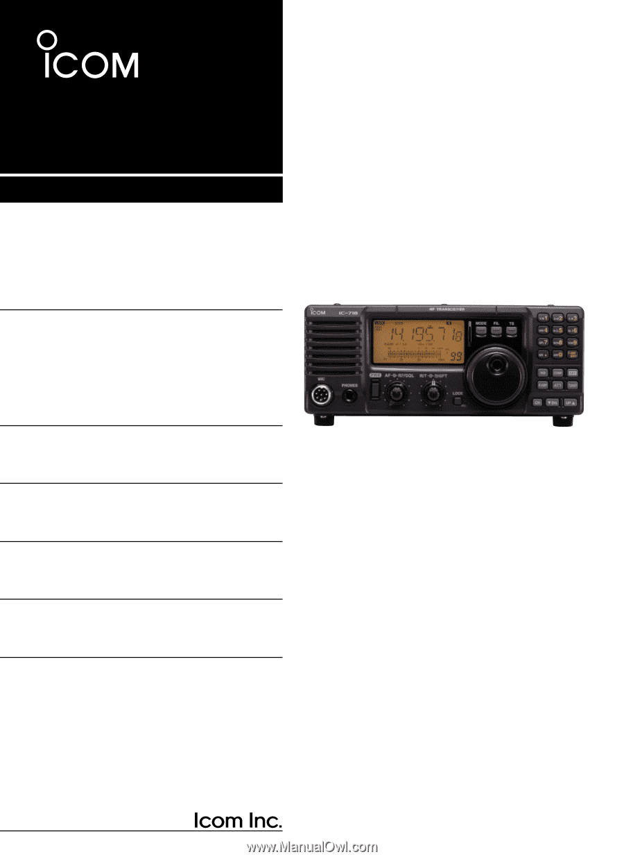
INSTRUCTION MANUAL
HF ALL BAND TRANSCEIVER
i718
This device complies with Part 15 of the FCC rules. Operation is sub-
ject to the following two conditions: (1) This device may not cause
harmful interference, and (2) this device must accept any interference
received, including interference that may cause undesired operation.