Icom IC-718 Instruction Manual - Page 8
Rear panel - power supply
 |
View all Icom IC-718 manuals
Add to My Manuals
Save this manual to your list of manuals |
Page 8 highlights
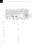
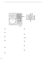
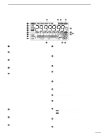
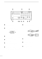
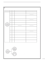
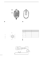
2 PANEL DESCRIPTION s Rear panel q w e 13 9 10 11 12 5678 1234 !0 oi u y tr q ANTENNA TERMINAL [ANT] (p. 10) Connects a 50 Ω antenna with a PL-259 connector and a 50 Ω coaxial cable. w DC POWER SOCKET [DC 13.8V] (p. 12) Accepts 13.8V DC through the supplied DC power cable. u ELECTRONIC KEYER JACK [KEY] Accepts a paddle to activate the internal electronic keyer. • Selection between the internal electronic keyer and straight key operation can be made in initial set mode. When connecting (⊕) a straight key Rear panel view e TUNER CONTROL SOCKET [TUNER] (p. 14) Accepts the control cable from an optional AH-4 AUTOMATIC ANTENNA TUNER. r CI-V REMOTE CONTROL JACK [REMOTE] (p. 57) Designed for use with a personal computer for remote operation of transceiver functions. t EXTERNAL SPEAKER JACK [EXT SP] (p. 11) Connects an 8 Ω external speaker, if desired. • When an external speaker is connected, the internal speaker does not function. y ACCESSORY SOCKET [ACC] (p. 7) Enables connection to external equipment such as an optional AT-180 AUTOMATIC ANTENNA TUNER, a TNC for data communications or a liner amplifier, etc. When connecting a paddle (dot) (com) (dash) i ALC INPUT JACK [ALC] Connects to the ALC output jack of a non-Icom linear amplifier. o SEND CONTROL JACK [SEND] (p. 14) Goes to ground while transmitting to control external equipments such as a liner amplifier. • Max. control level: 16 V DC/2 A !0 GROUND TERMINAL [GND] (p. 9) Connects the terminal to ground. 6
-
 1
1 -
2
-
 3
3 -
 4
4 -
 5
5 -
 6
6 -
 7
7 -
 8
8 -
 9
9 -
 10
10 -
 11
11 -
 12
12 -
 13
13 -
14
-
15
-
16
-
17
-
18
-
19
-
20
-
21
-
22
-
23
-
24
-
25
-
26
-
27
-
28
-
29
-
30
-
31
-
32
-
33
-
34
-
35
-
36
-
37
-
38
-
39
-
40
-
41
-
42
-
43
-
44
-
45
-
46
-
47
-
48
-
49
-
50
-
51
-
52
-
53
-
54
-
55
-
56
-
57
-
58
-
59
-
60
-
61
-
62
 |
 |
