Icom IC-718 Instruction Manual - Page 53
AT-180 internal switch description - hf all band transceiver
 |
View all Icom IC-718 manuals
Add to My Manuals
Save this manual to your list of manuals |
Page 53 highlights
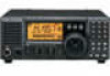
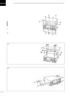
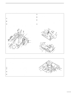
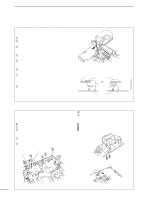
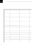
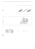
9 INSTALLATION AND CONNECTIONS s AT-180 internal switch description The optional AT-180 has 3 operating conditions for HF band operation. Select a suitable condition according to your antenna system. ➀ Remove the top cover of the AT-180. ➁ Set the tuner switches to the desired positions according to the table below. SW Position Operation A The tuner operating condition is set by S2 (default) described below. S1 THROUGH INHIBIT The tuner tunes the antenna even when the antenna has poor SWR (up to VSWR 3:1 after tuning). In this case, manual tuning is necessary each time you change the B frequency although the tuner automatically starts tuning when the VSWR is higher than 3:1. This setting is called "through inhibit," however, the tuner is set to "through" if the VSWR is higher than 3:1 after tuning. TUNER SENSITIVE CONDITION The tuner tunes each time you transmit C (except SSB mode). Therefore, the lowest SWR is obtained at any given time. For SSB mode, the same condition is as the "D" position below. S2 NORMAL CONDITION D The tuner tunes when the SWR is higher (default) than 1.5:1. Therefore, the tuner activates only when tuning is necessary. • AT-180 inside top cover S2 S1 DC BA • Specifications for the AT-180 • Frequency coverage : 1.9 - 54 MHz • Input impedance : 50 Ω • Maximum input : 120 W power • Minimum tuning : 8 W power • Matching impedance : 16.7-150 Ω (HF band) range 20 -125 Ω (50 MHz band) • Tuning accuracy : Less than SWR 1.5:1 • Insertion loss : Less than 1.0 dB (after tuning) • Power supply : 13.8 V DC/1 A (supplied from requirements the transceiver's ACC socket) • Dimensions (mm/in) : 167(W) × 58.6(H) × 225(D) 69⁄16(W) × 25⁄17(H) × 87⁄8(D) • Weight : 2.4 kg; 5 lb 4 oz • Supplied accessories : coaxial cable (1 m), ACC cable (DIN 13 pins) • Connector information for ACC(2) socket 2 4 5 1 3 6 7 ACC 2 PIN NO./ NAME DESCRIPTION ➀8 V Regulated 8 V output. (10 mA max.) ➁ GND Connects to ground. ➂ SEND Input/output pin. Goes to ground when transmitting (20 mA max). When grounded, transmits. ➃ BAND Band voltage output. (Varies with amateur band; 0 to 8.0 V). ➄ ALC ALC output voltage (-4 to 0 V). ➅ NC No connection. ➆ 13.8V 13.8 V output when power is ON (1 A max). 51
-
 1
1 -
2
-
3
-
4
-
5
-
6
-
7
-
8
-
9
-
10
-
11
-
12
-
13
-
14
-
15
-
16
-
17
-
18
-
19
-
20
-
21
-
22
-
23
-
24
-
25
-
26
-
27
-
28
-
29
-
30
-
31
-
32
-
33
-
34
-
35
-
36
-
37
-
38
-
39
-
40
-
41
-
42
-
43
-
44
-
45
-
46
-
47
-
 48
48 -
 49
49 -
 50
50 -
 51
51 -
 52
52 -
 53
53 -
 54
54 -
 55
55 -
 56
56 -
 57
57 -
 58
58 -
59
-
60
-
61
-
62
 |
 |
