Icom IC-718 Instruction Manual - Page 6
Front panel - dsp
 |
View all Icom IC-718 manuals
Add to My Manuals
Save this manual to your list of manuals |
Page 6 highlights
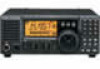
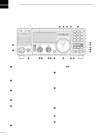
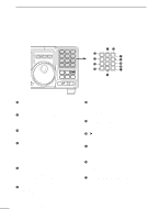
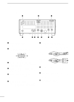
2 PANEL DESCRIPTION s Front panel (continued) MODE FILTER TS K 1 2 3 V/M A=B A/B 4 5 6 MW M =CL M V 7 SPL .NR 8 SCN 0 ANF 9 VOX F-INP ENT NB COMP SET P.AMP ATT TUNER CH √ DN UP ∫ ˛ ˛ #3 #2 @2 1 2 3 V/M A=B A/B #1 @3 4 5 6 MW M =CL M V #0 @4 7 8 9 SPL SCN VOX @9 @5 . 0 F-INP NR ANF ENT @8 @7 @6 @2 VFO/MEMORY SWITCH/1 [V/M•1] (pgs. 16, 35) ➥ Toggles the operating mode between VFO mode or memory mode when pushed. @3 MEMORY WRITE SWITCH/4 [MW•4] (p. 36) ➥ Stores the displayed frequency and operating mode into the selected memory channel when pushed for 1 sec. @4 SPLIT SWITCH/7 [SPL•7] (p. 30) Turns the split frequency operation ON or OFF when pushed. @5 NR SWITCH/. [NR• . ] (p. 23) ➥ Toggles the optional noise reduction function ON or OFF when pushed. Functions in all modes. • An optional UT-106 DSP UNIT is required. • [NR] appears on the display. ➥ Enters noise reduction level set mode when pushed for 1 sec. @6 ANF SWITCH/0 [ANF•0] (p. 23) Toggles the Automatic Notch Filter function ON or OFF. Functions in SSB and AM modes. • An optional UT-106 DSP UNIT is required. • [ANF] appears on the display. @7 FRQUENCY INPUT/ENTER SWITCH [F-INP/ENT] ➥ [F-INP/ENT], then keypad then [F-INP/ENT] - Direct frequency input. (p. 17) ➥ [CH] then [F-INP/ENT], then keypad then [FINP/ENT]. Push [CH]. - Direct memory number selection. (p. 35) @8 SCAN SWITCH/8 [SCAN•8] (p. 39) ➥ Push momentarily to start/stop the programmed scan in VFO mode. ➥ Push momentarily to start/stop the memory scan in memory mode. @9 VOX SWITCH/9 [VOX•9] (p. 27) ➥ Turn the VOX function ON or OFF when pushed in SSB modes. #0 M≈V SWITCH/6 [MV•6] (p. 37) ➥ Transfers the memory contents to VFO when pushed for 1 sec. #1 MEMORY CLEAR SWITCH/5 [M=CL•5] (p. 38) Clears the selected readout memory channel contents when pushed for 1 sec. in memory mode. • [BLANK] appears above the memory channel number. #2 VFO SELECT SWITCH/3 [A/B•3] (p. 16) ➥ Toggles between VFO A or VFO B in VFO mode. ➥ Toggles between transmission VFO and reception VFO during split operation. #3 VFO EQUALIZATION SWITCH/2 [A=B•2] Equalize the frequency and operating mode of the two VFO's. • The VFO B frequency and operating mode are equalized with the VFO A frequency and operating mode. 4
-
 1
1 -
 2
2 -
 3
3 -
 4
4 -
 5
5 -
 6
6 -
 7
7 -
 8
8 -
 9
9 -
 10
10 -
 11
11 -
 12
12 -
13
-
14
-
15
-
16
-
17
-
18
-
19
-
20
-
21
-
22
-
23
-
24
-
25
-
26
-
27
-
28
-
29
-
30
-
31
-
32
-
33
-
34
-
35
-
36
-
37
-
38
-
39
-
40
-
41
-
42
-
43
-
44
-
45
-
46
-
47
-
48
-
49
-
50
-
51
-
52
-
53
-
54
-
55
-
56
-
57
-
58
-
59
-
60
-
61
-
62
 |
 |
