Icom IC-R20 Service Manual - Page 20
Port allocations, LOGIC unit; IC3, Continued, 5-1 MAIN CPU PORT ALLOCATIONS
 |
View all Icom IC-R20 manuals
Add to My Manuals
Save this manual to your list of manuals |
Page 20 highlights
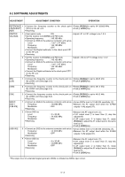
4-5 PORT ALLOCATIONS 4-5-1 MAIN CPU PORT ALLOCATIONS (LOGIC UNIT; IC3) Pin Port number name Description 3 DATAC Outputs data and clock control signal. 8 CLS1 9 CLS0 Output clock shift signals. Input port for the detecting signal whether the external power supply is 46 HVDET connecting or not. Low : The external power supply is connected. Outputs control signal to the AF ampli- 17 AFON fier. 18 POWER Input port for [POWER] key. 19 B_AMUTE Outputs B-band mute control signal. High : While B-band is muting. Outputs A-BAND de-emphasis control 20 A_AF_THURU signal. 21-24 A_DUD A_DCK B_DUD B_DCK Input ports for [A-DIAL]/[B-DIAL]. Input port for [SQL] switch. 25 SQL Low : While [SQL] switch is pushed. Outputs REC unit regulator control sig26 SUB_3C nal. High : While recording or playing. 31 A_VCO1 Outputs A-BAND's 1st LO control signal. 34 VRSTR Outputs strobe signals for volume. 36 REC Outputs recording LED control signal. Outputs charging current control sig38 CHGS nal. High : While rapid charging. 39 CHGC Outputs charger circuit control signal. High : While charging. 40 +3S Outputs +3S regulator control signal. Outputs LCD back light control signal. 41 LIGHT Low : Lights ON. 42 LD1 Outputs strobe signals to the expander IC (RF unit; IC14, pin 15). Outputs BAND2 selecting signal in the 43 B2C HF band. 44 B3C Outputs BAND3 selecting signal in the HF band. 45 B1C Outputs BAND1 selecting signal in the HF band. Outputs HF band selecting signal at A- 46 HFC BAND. 47 PLLDATA Outputs data signal to the PLL IC. (LOGIC unit; IC3)-Continued Pin number 48 Port name STR2 Description Outputs strobe signal to the D/A converter IC (IC22, pin 1). 49-52 KS3-KS1 Output key matrix signals. • Input port for the matrix signal. 53 I1 • Outputs power ON/OFF control sigPCON nal. 54 L0 B_TCON • Input port for the matrix signal. • Outputs B-RTONE filter amplifier control signal. 55-61 KR5-KR0 Input ports for key matrix 63 B_AF_THURU Outputs B-BAND de-emphasis control signal. 64 PLLASTB Outputs strobe signals to the A-BAND 1st LO circuit. Outputs strobe signals to the A-BAND 65 PLLCSTB 2nd LO circuit. 66 PLLESTB Outputs strobe signals to CONVERTER LO circuit. the DOWN Outputs A-BAND power supply circuit 67 A_R3C control signal. Low : While A-BAND receiving. 68 PLLCK Outputs clock signal to the PLL IC. 69 PLLDSTB Outputs strobe signals to the B-BAND 2nd LO circuit. Outputs strobe signals to the B-BAND 70 PLLBSTB 1st LO circuit. 71 A_TCON Outputs A-RTONE filter amplifier control signal. 72 LCD_CS Outputs LCD chip select signal. 74 BFOC Outputs BFO control signal. Low : While SSB is receiving. Outputs B-BAND power supply circuit 75 B_R3C control signal. Low : While B-BAND receiving. 76 LCD_RESET Outputs reset signal to the LCD. 77 LCD_RS Outputs command and data signals to the LCD. Outputs strobe signals to the expander 78 LD2 IC (RF unit; IC20, pin 15). 79-81 B_VCO2 B_VCO3 B_VCO4 Output B-BAND 1st LO circuit control signals. 98 ECK Outputs clock signal to the EEPROM (IC1, pin 6). I/O port for data signal from/to the 99 ESIO EEPROM (IC1, pin 5). 4 - 12
-
 1
1 -
2
-
3
-
4
-
5
-
6
-
7
-
8
-
9
-
10
-
11
-
12
-
13
-
14
-
 15
15 -
 16
16 -
 17
17 -
 18
18 -
 19
19 -
 20
20 -
 21
21 -
 22
22 -
 23
23 -
 24
24 -
 25
25 -
26
-
27
-
28
-
29
-
30
-
31
-
32
-
33
-
34
-
35
-
36
-
37
-
38
-
39
-
40
-
41
-
42
-
43
-
44
-
45
-
46
-
47
-
48
-
49
-
50
-
51
-
52
-
53
-
54
-
55
-
56
-
57
-
58
-
59
-
60
-
61
-
62
-
63
-
64
-
65
-
66
-
67
-
68
-
69
-
70
 |
 |
