Icom IC-R20 Service Manual - Page 22
BC-156 circuit description, 6-1 DC/DC CONVERTER CIRCUIT MAIN UNIT, 6-2 CHARGING CIRCUIT
 |
View all Icom IC-R20 manuals
Add to My Manuals
Save this manual to your list of manuals |
Page 22 highlights
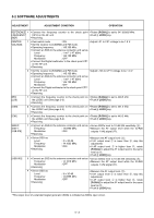
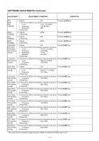
4-6 BC-156 CIRCUIT DESCRIPTION 4-6-1 DC/DC CONVERTER CIRCUIT (MAIN UNIT) Input voltage (8-16 V) from the BC-123A/E pass through reverse protection circuit (D6) via the J1. The voltage pass through the current limiter (R19) which can pass less than 2.0 A via the fuse (F1), and is then applied to the DC/DC converter circuit (IC2, Q7, D2, L1 and C4). The circuit converts 8-16 V input voltage to obtain approximately 5.2 V/2 A, and the converted voltage is applied to the charging circuit (IC1, Q1). • DC/DC CONVERTER CIRCUIT from the BC-123A/E Protection circuit D6 Current limiter DC/DC F1 R19 converter IC1, Q7, D2, L4, C1 to the charging circuit 4-6-2 CHARGING CIRCUIT (MAIN UNIT AND TANSHI BOARD) The converted voltage from the DC/DC converter circuit is applied to the charging circuit (MAIN unit; IC1, Q1), and is then applied to the TANSHI board via the J4, pins 1 and 2 (MAIN unit) as "CHGOUT" signal. The signal passes through the charging current detector (R1), and is then applied to the charging selector (TANSHI board; RL1) which is controlled by "CONT" signal. The signal is then applied to the CP1 (TANSHI board) as "SBATT+" signal or CP4 as "BATT+" signal. A part of "CHGOUT" signal is applied to the charging circuit (IC1, pins 13 and 14) via the J1, pin 6 (TANSHI board) to control battery charging. 4-6-3 CHARGING CONTROL CIRCUIT (MAIN UNIT AND TANSHI BOARD) • CHARGING THE BATTERY WITH IC-R20 The "DET2" signal from the TANSHI board is applied to the D5 (MAIN unit) via the J4 (MAIN unit), and is then applied to the Q4 (MAIN unit). As Q4 turns ON, the output signal from Q4 is applied to the D4. The signal is applied to the Q3 to turn ON, then the output signal from Q3 is applied to the charging control IC (MAIN unit; IC1, pin 2). The IC controls Q1's base voltage to keep stable voltage/current battery charging. A part of signal from Q4 (MAIN unit) is applied to the charging selector circuit (TANSHI board; RL1) via the J1, pin 8 (TANSHI board) as "CONT" signal. • CHARGING THE BATTERY ONLY The "DET1" signal from the TANSHI board is applied to the D5 (MAIN unit) via the J4 (MAIN unit), and is then applied to the Q2 (MAIN unit). As Q2 turns ON, the output signal from Q2 is applied to the D4. The signal is applied to the Q3 to turn ON, then the output signal from Q3 is applied to the charging control IC (MAIN unit; IC1, pin 2). The IC controls Q1's base voltage to keep stable voltage/current battery charging. • CHARGING CIRCUIT MAIN UNIT Converted 5.2 V/2 A Charging circuit IC1, Q1 TANSHI BOARD "DET1" signal to D5 (MAIN unit) Current detector R1 Selector RL1 "CONT" signal from Q6 (MAIN unit) "DET2" signal to D5 (MAIN unit) • CHARGING CONTROL CIRCUIT 5.2 V/2 A from the DC/DC converter circuit D1 Q1 "CHGOUT" signal to the charger selector (RL1) Q2 Charging Q3 controller Q4 IC1 D4 D5 CP3 (DET1) CP2 (SBATT ) CP1 (SBATT+) CP4 (BATT+) CP5 (BATT ) CP6 (DET2) CP3 (DET1) CP6 (DET2) 4 - 14
-
 1
1 -
2
-
3
-
4
-
5
-
6
-
7
-
8
-
9
-
10
-
11
-
12
-
13
-
14
-
15
-
16
-
 17
17 -
 18
18 -
 19
19 -
 20
20 -
 21
21 -
 22
22 -
 23
23 -
 24
24 -
 25
25 -
 26
26 -
 27
27 -
28
-
29
-
30
-
31
-
32
-
33
-
34
-
35
-
36
-
37
-
38
-
39
-
40
-
41
-
42
-
43
-
44
-
45
-
46
-
47
-
48
-
49
-
50
-
51
-
52
-
53
-
54
-
55
-
56
-
57
-
58
-
59
-
60
-
61
-
62
-
63
-
64
-
65
-
66
-
67
-
68
-
69
-
70
 |
 |
