Icom IC-R20 Service Manual - Page 24
Software adjustments, R-DIAL], LOCK], ADJUSTMENT, ADJUSTMENT CONDITION, OPERATION
 |
View all Icom IC-R20 manuals
Add to My Manuals
Save this manual to your list of manuals |
Page 24 highlights
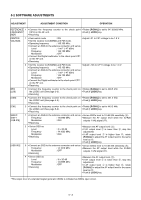
5-2 SOFTWARE ADJUSTMENTS ADJUSTMENT ADJUSTMENT CONDITION OPERATION REFERENCE 1 • Connect the frequency counter to the check point • Rotate [R-DIAL] to set to 247.05000 MHz. FREQUENCY CP18 on the RF unit. • Push [• LOCK] key. [REF] • Receiving CENTER VOLTAGE 1 • Dual watch mode : ON • Adjust L21 to CP1 voltage to be 1.0 V. • Set the receiver to [A-BAND] and FM mode. • Operating frequency : 145.100 MHz • Connect an SSG to the antenna connector and set as Level : 1 mV* (-47 dBm) Frequency : 145.100 MHz Modulation : OFF • Connect the Digital multimeter to the check point CP1 on the RF unit. • Receiving 2 • Set the receiver to [B-BAND] and FM mode. • Adjust L105 to CP11 voltage to be 1.0 V. • Operating frequency : 145.100 MHz • Connect an SSG to the antenna connector and set as Level : 1 mV* (-47 dBm) Frequency : 145.100 MHz Modulation : OFF • Connect the Digital multimeter to the check point CP11 on the RF unit. • Receiving BFO [LSB] 1 • Connect the frequency counter to the check point on • Rotate [R-DIAL] to set to 448.5 kHz. the LOGIC unit (See page 5-3). • Push [• LOCK] key. • Receiving [USB] 2 • Connect the frequency counter to the check point on • Rotate [R-DIAL] to set to 451.5 kHz. the LOGIC unit (See page 5-3). • Push [• LOCK] key. • Receiving [CW] 3 • Connect the frequency counter to the check point on • Rotate [R-DIAL] to set to 449.2 kHz. the LOGIC unit (See page 5-3). • Push [• LOCK] key. • Receiving SSB-IF SHIFT [LSB-IFS] 1 • Connect an SSG to the antenna connector and set as • Set an SSG's level to 10 dB S/N sensitivity (A). Frequency : 14.0990 MHz • Measure the AF output level while the IC-R20 Modulation : OFF outputs 1 kHz signal (B). • Receiving 2 • Set an SSG as Level Frequency Modulation • Receiving : A+ 35 dB : 14.1005 MHz : OFF • Measure the AF output level (C). • If AF output level C is lower than B, skip this adjustment. • If AF output level C is higher than B, rotate [R-DIAL] to adjust the AF output level to the same level as B. • Push [• LOCK] key. [USB-IFS] 3 • Connect an SSG to the antenna connector and set as • Set an SSG's level to 10 dB S/N sensitivity (A). Frequency : 14.1010 MHz • Measure the AF output level while the IC-R20 Modulation : OFF outputs 1 kHz signal (B). • Receiving 4 • Set an SSG as Level Frequency Modulation • Receiving : A+ 35 dB : 14.0995 MHz : OFF • Measure the AF output level (C). • If AF output level C is lower than B, skip this adjustment. • If AF output level C is higher than B, rotate [R-DIAL] to adjust the AF output level to the same level as B. • Push [• LOCK] key. *This output level of a standard signal generator (SSG) is indicated as SSG's open circuit. 5 - 2
-
 1
1 -
2
-
3
-
4
-
5
-
6
-
7
-
8
-
9
-
10
-
11
-
12
-
13
-
14
-
15
-
16
-
17
-
18
-
 19
19 -
 20
20 -
 21
21 -
 22
22 -
 23
23 -
 24
24 -
 25
25 -
 26
26 -
 27
27 -
 28
28 -
 29
29 -
30
-
31
-
32
-
33
-
34
-
35
-
36
-
37
-
38
-
39
-
40
-
41
-
42
-
43
-
44
-
45
-
46
-
47
-
48
-
49
-
50
-
51
-
52
-
53
-
54
-
55
-
56
-
57
-
58
-
59
-
60
-
61
-
62
-
63
-
64
-
65
-
66
-
67
-
68
-
69
-
70
 |
 |
