Icom IC-R20 Service Manual - Page 23
Adjustment procedures, Preparation
 |
View all Icom IC-R20 manuals
Add to My Manuals
Save this manual to your list of manuals |
Page 23 highlights
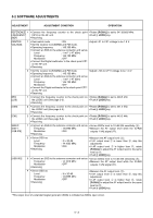
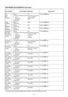
SECTION 5 ADJUSTMENT PROCEDURES 5-1 PREPARATION Almost adjustments must be adjusted on the adjustment mode. The shorten plug (see below) is required when entering the adjustment mode. ' REQUIRED TEST EQUIPMENT EQUIPMENT DC power supply Frequency counter GRADE AND RANGE Output voltage : 6.0 V DC Current capacity : 1 A or more Frequency range : 0.1-1000 MHz Frequency accuracy : ±1 ppm or better Sensitivity : 100 mV or better EQUIPMENT Digital multimeter Standard signal generator (SSG) GRADE AND RANGE Input impedance : 10 kΩ/V DC or better Frequency range Output level : 0.1-3000 MHz : 0.1 µV-32 mV (-127 to -17 dBm) ' ENTERING THE ADJUSTMENT MODE q Connect the shorten plug to the [SP] jack. w Push and hold [8 SET], [MR S.MW], [BAND] and [MAIN/SUB] keys, and then turn power ON. NOTE: Entering adjustment mode, keep on entering adjustment mode until dis-connect the shorten plug and turn power OFF. I OPERATION ON THE ADJUSTMENT MODE Change the adjustment channel or item [UP] : [MR S.MW] key Change the adjustment channel or item [DOWN] : [SCOPE] key Change the adjustment value : [R-DIAL] While entering adjustment mode, some adjustments must push [• LOCK] or [8 SET] keys to write the adjustment value to the CPU. Refer to following list in detail. KEY [• LOCK] [8 SET] OPERATION Write the REFERENCE FREQUENCY ADJUSTMENT value. Write the BFO ADJUSTMENT value. Write the AFC ADJUSTMENT value. Write the TRACKING ADJUSTMENT value. Write the S-METER ADJUSTMENT value. ' CONNECTIONS Standard signal generator to the antenna connector 0.1 V to 32 mV ( 127 dBm to 17 dBm) JIG Shorten I/O and GND line. 3.5(d) mm I/O GND 3-conductor 3.5(d) mm plug must be used. to [SP] jack Power supply to [DC] jack 6 V / 1 A IC-R20 5 - 1
-
 1
1 -
2
-
3
-
4
-
5
-
6
-
7
-
8
-
9
-
10
-
11
-
12
-
13
-
14
-
15
-
16
-
17
-
 18
18 -
 19
19 -
 20
20 -
 21
21 -
 22
22 -
 23
23 -
 24
24 -
 25
25 -
 26
26 -
 27
27 -
 28
28 -
29
-
30
-
31
-
32
-
33
-
34
-
35
-
36
-
37
-
38
-
39
-
40
-
41
-
42
-
43
-
44
-
45
-
46
-
47
-
48
-
49
-
50
-
51
-
52
-
53
-
54
-
55
-
56
-
57
-
58
-
59
-
60
-
61
-
62
-
63
-
64
-
65
-
66
-
67
-
68
-
69
-
70
 |
 |
