Icom IC-R20 Service Manual - Page 21
D/a Converter Ic Port Allocations
 |
View all Icom IC-R20 manuals
Add to My Manuals
Save this manual to your list of manuals |
Page 21 highlights
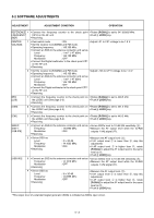
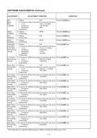
4-5-2 SUB CPU PORT ALLOCATIONS (REC UNIT; IC2) Pin number 18 Port name RSTO Description Input port for the USB reset signal. 19 PWREN Input port for the USB suspend signal. 24 FIFOST Outputs recording/playing select signal. Input port for the ADPCM command 25 CBUSY waiting signal. 26-28 EMP MID FUL Input ports for the ADPCM buffer signals. 35 36 B_SQL A_SQL Output recording mute signals. Input port for the power supply verify25 SUB_3C ing signal. 4-5-3 EXPANDER IC PORT ALLOCATIONS (RF UNIT; IC22) Pin number 4 Port name Description DOWN_CONV Outputs signal. the down converter control 5 2GLO Outputs 2002 MHz LO select signal for the down converter. 6 1GLO Outputs 1001 MHz LO select signal for the down converter. 7 ANTSW Outputs the bar antenna select signal. High : The bar antenna is selected. Outputs the power save control signal to the A-BAND circuit. 11 APS Low : While the A-BAND circuit is power saving. 12 A_WFM Outputs WFM mode select signal at the A-BAND circuit. 13 NBC Outputs noise blanker control signal. Outputs the power save control signal 14 BPS to the B-BAND circuit. Low : While the B-BAND circuit is power saving. 4-5-4 D/A CONVERTER IC PORT ALLOCATIONS (RF UNIT; IC14) Pin number 2 Port name Description A_VHFC Outputs VHF band selecting signal at the A-BAND circuit. Outputs 300 MHz band selecting sig3 A_300MC nal at the A-BAND circuit. 4 A_UHFC Outputs UHF band selecting signal at the A-BAND circuit. Outputs the A-BAND 1st LO circuit 6 A_VCO3 control signal. 7 A_NFMC Outputs narrow FM mode selecting signal at the A-BAND circuit. Outputs ANL (Automatic Noise Limiter) 13 A_ANLC control signal at A-BAND circuit. High : While ANL is ON. Outputs AM mode selecting signal at 18 A_AMC the A-BAND circuit. 19 SSBC Outputs narrow SSB mode selecting signal at the A-BAND circuit. 4-5-5 D/A CONVERTER IC PORT ALLOCATIONS (RF UNIT; IC20) Pin number 2 Port name Description B_VHFC Outputs VHF band selecting signal at the B-BAND circuit. 3 B_UHFC Outputs UHF band selecting signal at the B-BAND circuit. 4 B_GC Outputs GHz band selecting signal at the B-BAND circuit. 5 B-800MC Outputs 800 MHz band selecting signal at the B-BAND circuit. Outputs wide FM mode selecting sig7 A_WFMC nal at the B-BAND circuit. 8 B_VCO1 Outputs the B-BAND control signal. 1st LO circuit Outputs ANL (Automatic Noise Limiter) 9 B_ANLC control signal at B-BAND circuit. High : While B-BAND ANL is ON. 18 A_AMC Outputs AM mode selecting signal at the B-BAND circuit. Outputs narrow AM or narrow FM 19 B_AM_FM mode selecting signal at the B-BAND circuit. 4 - 13
-
 1
1 -
2
-
3
-
4
-
5
-
6
-
7
-
8
-
9
-
10
-
11
-
12
-
13
-
14
-
15
-
 16
16 -
 17
17 -
 18
18 -
 19
19 -
 20
20 -
 21
21 -
 22
22 -
 23
23 -
 24
24 -
 25
25 -
 26
26 -
27
-
28
-
29
-
30
-
31
-
32
-
33
-
34
-
35
-
36
-
37
-
38
-
39
-
40
-
41
-
42
-
43
-
44
-
45
-
46
-
47
-
48
-
49
-
50
-
51
-
52
-
53
-
54
-
55
-
56
-
57
-
58
-
59
-
60
-
61
-
62
-
63
-
64
-
65
-
66
-
67
-
68
-
69
-
70
 |
 |
