Intel DQ67EP English Product Guide
Intel DQ67EP Manual
 |
View all Intel DQ67EP manuals
Add to My Manuals
Save this manual to your list of manuals |
Intel DQ67EP manual content summary:
- Intel DQ67EP | English Product Guide - Page 1
Intel® Desktop Board DQ67EP Product Guide Order Number: G15491-001 - Intel DQ67EP | English Product Guide - Page 2
Revision History Revision -001 Revision History First release of the Intel® Desktop Board DQ67EP Product Guide Date December 2010 Disclaimer INFORMATION IN THIS DOCUMENT IS PROVIDED IN CONNECTION WITH INTEL® PRODUCTS. NO LICENSE, EXPRESS OR IMPLIED, BY ESTOPPEL OR OTHERWISE, TO ANY INTELLECTUAL - Intel DQ67EP | English Product Guide - Page 3
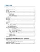
by Intel. Document Organization The chapters in this Product Guide are arranged as follows: 1 Desktop Board Features: a summary of product features 2 Installing and Replacing Desktop Board Components: instructions on how to install the Desktop Board and other hardware components 3 Updating the BIOS - Intel DQ67EP | English Product Guide - Page 4
Intel Desktop Board DQ67EP Product Guide Terminology The table below gives descriptions of some common terms used in the product guide. Term Description GB Gigabyte (1,073,741,824 bytes) GHz Gigahertz (one billion hertz) KB Kilobyte (1024 bytes) MB Megabyte (1,048,576 bytes) Mb Megabit - Intel DQ67EP | English Product Guide - Page 5
Desktop Board Components 12 Processor ...14 Intel® Q67 Express Chipset 15 Main Memory...15 Graphics Subsystem 16 Integrated Graphics 16 DisplayPort 16 Digital Visual Interface 16 PCI Express* x16 Graphics 17 Audio Subsystem 17 LAN Subsystem 18 USB Support ...19 SATA Support...19 SATA RAID - Intel DQ67EP | English Product Guide - Page 6
Intel Desktop Board DQ67EP Product Guide Installing and Removing a Processor 37 Installing a Processor 37 Installing a Processor Fan Heat Sink 41 Connecting the Processor Fan Heat Sink Cable 41 Removing the Processor 41 Installing and Removing System Memory 42 Installing DIMMs 43 Removing - Intel DQ67EP | English Product Guide - Page 7
50 21. Back Panel Audio Connectors 55 22. Location of the System Fan Header 56 23. Connecting Power Supply Cables 57 24. Location of the BIOS Configuration Jumper Block 58 25. Removing the Battery 65 26. Intel Desktop Board DQ67EP China RoHS Material Self Declaration Table 80 vii - Intel DQ67EP | English Product Guide - Page 8
Intel Desktop Board DQ67EP Product Guide Tables 1. Feature Summary 9 2. Intel Desktop Board DQ67EP Components 13 3. LAN Status LEDs States 18 4. Master Key and User Hard Disk Drive Password Functions 22 5. Front Panel Audio Signal Names for Intel HD Audio 51 6. Front Panel Audio Header Signal - Intel DQ67EP | English Product Guide - Page 9
Desktop Board DQ67EP. Table 1 summarizes the major features of the Desktop Board. Table 1. Feature Summary Form Factor Processor Support Mini-ITX (170.18 millimeters [6.7 inches] x 170.18 millimeters [6.7 inches]) • Intel® Core™ i7, Intel® Core™ i5, Intel® Core™ i3, and Intel® Pentium processors - Intel DQ67EP | English Product Guide - Page 10
Intel Desktop Board DQ67EP Product Guide Table 1. Feature Summary (continued) Peripheral Interfaces LAN Support • Twelve USB ports: ― Two USB 3.0 ports are implemented with stacked back panel connectors (blue) ― Four USB 2.0 ports are implemented with stacked back panel connectors (black) ― - Intel DQ67EP | English Product Guide - Page 11
Desktop Board Features Supported Operating Systems The Desktop Board supports the following operating systems: • Microsoft Windows* 7 Ultimate 64-bit edition • Microsoft Windows 7 Ultimate 32-bit edition • Microsoft Windows 7 Professional 64-bit edition • Microsoft Windows 7 Professional - Intel DQ67EP | English Product Guide - Page 12
Intel Desktop Board DQ67EP Product Guide Desktop Board Components Figure 1 shows the approximate location of the major components on Intel Desktop Board DQ67EP. Figure 1. Intel Desktop Board DQ67EP Components 12 - Intel DQ67EP | English Product Guide - Page 13
Board Features Table 2. Intel Desktop Board DQ67EP Components Label A B C D E F G H I J K L M N O P Q R S T U V W X Y Z AA Description Back panel connectors Battery Serial port header 12 V processor core voltage connector (2 x 2 pin) SATA connectors Front panel USB 2.0 header PCI Express Mini - Intel DQ67EP | English Product Guide - Page 14
Guide Online Support For more information on Intel Desktop Board DQ67EP consult the following online resources: • Intel Desktop Board DQ67EP • Desktop Board Support • Available configurations for Intel Desktop Board DQ67EP • Supported processors • Chipset information • BIOS and driver updates - Intel DQ67EP | English Product Guide - Page 15
Desktop Board Features Intel® Q67 Express Chipset The Intel Q67 Express Chipset, consisting of the Intel Q67 Platform Controller Hub (PCH), provides interfaces to the processor and the USB, SATA, LPC, audio, network, display, and PCI Express interfaces. The PCH is a centralized controller for the - Intel DQ67EP | English Product Guide - Page 16
Intel Desktop Board DQ67EP Product Guide Graphics Subsystem The board supports either integrated graphics (Intel Graphics Technology) or PCI Express 2.0 x16 graphics. Integrated Graphics The board supports integrated graphics through the Intel® Flexible Display Interface (Intel® FDI) for processors - Intel DQ67EP | English Product Guide - Page 17
Desktop Board Features PCI Express* x16 Graphics The Intel Core i7, Intel Core i5, Intel Core i3, and Intel Pentium processors in an LGA1155 socket support discrete add-in graphics cards via the PCI Express 2.0 x16 add-in card connector. The board supports the following PCI Express speeds: • PCI - Intel DQ67EP | English Product Guide - Page 18
Intel Desktop Board DQ67EP Product Guide LAN Subsystem The LAN subsystem includes: • Intel 82579LM Gigabit (10/100/1000 Mb/s) Ethernet LAN controller with support for: ⎯ Intel AMT 7.0 ⎯ ASF 2.0 • RJ-45 LAN connector with integrated status LEDs LAN software and drivers are available at http:// - Intel DQ67EP | English Product Guide - Page 19
Desktop Board Features USB Support The Desktop Board supports USB 3.0 and USB 2.0. USB 3.0 is supported via two USB 3.0 ports (blue) on the back panel. USB 3.0 ports are backward compatible support requires both an operating system and drivers that fully support USB 2.0 transfer rates. NOTE Intel - Intel DQ67EP | English Product Guide - Page 20
Intel Desktop Board DQ67EP Product Guide SATA RAID The Intel Q67 PCH supports Intel® Rapid Storage Technology (Intel® RST) which enables the following RAID (Redundant Array of Independent Drives) levels: • RAID 0 - data striping • RAID 1 - data mirroring • RAID 0+1 (or RAID 10) - data striping and - Intel DQ67EP | English Product Guide - Page 21
provides the Power-On Self-Test (POST), the BIOS Setup program, and the PCI/PCI Express and SATA auto-configuration utilities. The BIOS is stored in the Serial Peripheral Interface (SPI) Flash memory device. The BIOS can be updated by following the instructions in Chapter 3 starting on page 67. SATA - Intel DQ67EP | English Product Guide - Page 22
Intel Desktop Board DQ67EP Product Guide • If both the supervisor and user passwords are set, you must enter either the supervisor password or the user password to access Setup. Setup options are then available for viewing and changing depending on whether the supervisor or user password was - Intel DQ67EP | English Product Guide - Page 23
Desktop Board Features During every POST, if a User hard disk drive password is Security feature is not supported in PCH RAID mode. Secured hard disk drives attached to the system when the system is in PCH RAID mode will not be accessible due to the disabling of BIOS Hard Disk Drive Password - Intel DQ67EP | English Product Guide - Page 24
embedded in the Intel Q67 PCH • Intel 82579LM Gigabit (10/100/1000 Mb/s) Ethernet LAN controller • BIOS/SPI Flash (64 Mb) • Intel MEBX reset header • Intel® Centrino® Advanced-N 6200 Wireless Adapter (optional). For instructions for installing this PCI Express Half-Mini Card, see page - Intel DQ67EP | English Product Guide - Page 25
accounting costs. • System Defense 2 • Remote Configuration (RCFG) ⎯ Client Control Mode Setup and Configuration • KVM (Keyboard-Video-Mouse) Remote Control. KVM Remote Control requires the use of an Intel processor with integrated graphics. The maximum resolution supported by KVM Remote Control is - Intel DQ67EP | English Product Guide - Page 26
Intel Desktop Board DQ67EP Product Guide Intel® MEBX Reset Header This header (see Figure 3) allows you to reset the Intel AMT configuration to the factory defaults. Momentarily shorting pins 1 and 2 with a jumper (not supplied) will accomplish the following: • Return all Intel ME parameters to - Intel DQ67EP | English Product Guide - Page 27
PC Alarm Clock. For more information about Intel Fast Call for Help, go to http://software.intel.com/enus/articles/fast-call-for-help-overview/. Trusted Platform Module (TPM) The Nuvoton* WPCT210 TPM 1.2, revision 103 component on Intel Desktop Board DQ67EP is designed to enhance platform security - Intel DQ67EP | English Product Guide - Page 28
Intel Desktop Board DQ67EP Product Guide For information about enabling and activating the TPM, refer to the Trusted Platform Module (TPM) Quick Reference Guide included with the board. Fan Speed Control and Hardware Monitoring The features of the hardware monitoring and fan speed control include: • - Intel DQ67EP | English Product Guide - Page 29
. • All fan headers are controlled by Pulse Width Modulation. • The system fan supports Linear Fan Control on 3-wire fans. The Desktop Board has a 4-pin processor fan header and one 4-pin system fan header that is compatible with 4-wire and 3-wire fans. LAN Wake Capabilities CAUTION For LAN wake - Intel DQ67EP | English Product Guide - Page 30
Intel Desktop Board DQ67EP Product Guide The Desktop Board supports the PCI Bus Power Management Interface Specification. Add-in cards that support of Instantly Available PC technology requires operating system support and PCI Express add-in cards and drivers. +5 V Standby Power Indicator LED CAUTION - Intel DQ67EP | English Product Guide - Page 31
Desktop Board Features Wake from USB NOTE Wake from USB requires the use of a USB peripheral that supports Wake from USB and an operating system that supports Wake from USB. USB bus activity wakes the computer from an ACPI S3 state. PCI Express WAKE# Signal Wake-up Support When the WAKE# signal on a - Intel DQ67EP | English Product Guide - Page 32
Intel Desktop Board DQ67EP Product Guide 32 - Intel DQ67EP | English Product Guide - Page 33
how to: • Install the I/O shield • Install and remove the Desktop Board • Install and remove a processor • Install and remove memory • Install and remove a PCI Express x16 card • Install a Wireless LAN Card in the PCI Express Half-Mini Card Slot (optional) • Connect Serial ATA cables • Connect to - Intel DQ67EP | English Product Guide - Page 34
Intel Desktop Board DQ67EP Product Guide Installation Precautions When you install and test the Intel Desktop Board, observe all warnings and cautions in the installation instructions all warnings and cautions that instruct you to refer computer servicing to qualified technical personnel. Prevent - Intel DQ67EP | English Product Guide - Page 35
transmissions, protects internal components from dust and foreign objects, and promotes correct airflow within the chassis. Install the I/O shield before installing the Desktop Board in the chassis. Place the shield inside the chassis as shown in Figure 5. Press the shield into place so that it fits - Intel DQ67EP | English Product Guide - Page 36
Intel Desktop Board DQ67EP Product Guide Installing and Removing the Desktop Board CAUTION Only qualified manual for instructions on installing and removing the Desktop Board. Figure 6 shows the location of the mounting screw holes for Intel Desktop Board DQ67EP. Figure 6. Intel Desktop Board DQ67EP - Intel DQ67EP | English Product Guide - Page 37
Installing and Replacing Desktop Board Components Installing and Removing a Processor Instructions on how to install the processor on the Desktop Board are given below. Installing a Processor CAUTION Before installing or removing a processor, make sure the AC power has been removed by unplugging the - Intel DQ67EP | English Product Guide - Page 38
Intel Desktop Board DQ67EP Product Guide 3. Rotate the socket lever to lift the load plate away from the socket (Figure 8, A). Make sure that the load plate is in the fully open - Intel DQ67EP | English Product Guide - Page 39
Installing and Replacing Desktop Board Components 4. Remove the processor from its protective cover. Hold the processor only at the edges, being careful not to touch the bottom of the processor (see Figure 9). NOTE Do not discard the processor cover. Always replace the processor cover if you remove - Intel DQ67EP | English Product Guide - Page 40
Intel Desktop Board DQ67EP Product Guide 6. Carefully lower the socket lever (Figure 11, A) while making Load Plate in Place 7. Pick up the socket cover and remove it from the desktop board. NOTE Do not discard the socket cover; save it for possible future use. Always replace the socket cover if - Intel DQ67EP | English Product Guide - Page 41
Installing and Replacing Desktop Board Components Installing a Processor Fan Heat Sink Intel Desktop Board DQ67EP has mounting holes for a processor fan heat sink. For instructions on how to attach the processor fan heat sink to the Desktop Board, refer to the boxed processor manual or boxed thermal - Intel DQ67EP | English Product Guide - Page 42
Intel Desktop Board DQ67EP Product Guide Installing and Removing System Memory NOTE To be fully compliant with all applicable Intel SDRAM memory specifications, the board requires DIMMs that support the Serial Presence Detect (SPD) data structure. The desktop board has two 240-pin DDR3 DIMM sockets - Intel DQ67EP | English Product Guide - Page 43
Installing and Replacing Desktop Board Components Installing DIMMs To make sure you have the correct DIMM, place it on the illustration of the DDR3 DIMM in Figure 14. All the notches should match with the DDR3 DIMM. Figure 14. Use DDR3 DIMMs 43 - Intel DQ67EP | English Product Guide - Page 44
Intel Desktop Board DQ67EP Product Guide To install a DIMM, follow these steps: 1. Observe the precautions in "Before You Begin" on page 33. 2. Turn off all peripheral devices connected to the computer. - Intel DQ67EP | English Product Guide - Page 45
damaged. CAUTION Before installing a PCI Express add-in card, make sure that it will not touch the processor heatsink. This might cause an electrical short and damage the graphics card and/or the desktop board. CAUTION Before installing a PCI Express add-in card, make sure that the tabs on the DIMM - Intel DQ67EP | English Product Guide - Page 46
Intel Desktop Board DQ67EP Product Guide Follow these instructions to install a PCI Express x16 graphics card: 1. Observe the precautions in Figure 16, B). 4. Connect a monitor to the graphics card according to the manufacturer's instructions. Figure 16. Installing a PCI Express x16 Graphics Card 46 - Intel DQ67EP | English Product Guide - Page 47
Installing and Replacing Desktop Board Components Removing a PCI Express x16 Graphics Card Follow these instructions to remove a PCI Express x16 graphics card from a connector: 1. Observe the precautions in "Before You Begin" on page 33. 2. Disconnect the monitor cable from the - Intel DQ67EP | English Product Guide - Page 48
Intel Desktop Board DQ67EP Product Guide Installing a Wireless LAN Card in the PCI Express Half-Mini Card Slot (Optional) A wireless LAN card can be installed in the Desktop Board's PCI Express Half-Mini Card slot. Wireless LAN cards are not included with the Desktop Board and must be purchased - Intel DQ67EP | English Product Guide - Page 49
Components Connecting Serial ATA (SATA) Cables SATA cables support the Serial ATA protocol. Each cable can be used to connect one internal SATA drive to the Desktop Board. For correct cable function: 1. Observe the precautions in "Before You Begin" on page 33. 2. Attach one end of the SATA cable - Intel DQ67EP | English Product Guide - Page 50
Intel Desktop Board DQ67EP Product Guide Connecting to the Internal Headers Before connecting cables to any of the internal headers, observe the precautions in "Before You Begin" on page 33. Figure 20 shows the location of the internal headers and connectors on Intel Desktop Board DQ67EP. Figure 20. - Intel DQ67EP | English Product Guide - Page 51
Installing and Replacing Desktop Board Components Front Panel Audio Header The front panel audio header shown in Figure 20, A supports both Intel High Definition Audio and AC '97 Audio. Table 5 shows the pin assignments and signal names for HD Audio and Table 6 lists the pin assignments and - Intel DQ67EP | English Product Guide - Page 52
Intel Desktop Board DQ67EP Product Guide Front Panel USB 2.0 Headers Figure 20, C shows the location of the front panel USB 2.0 headers and Table 8 lists the pin assignments and signal names. Table 8. - Intel DQ67EP | English Product Guide - Page 53
Installing and Replacing Desktop Board Components Alternate Front Panel Power LED Header Figure 20, Out Out Intel FCFH Header Figure 20, F shows the location of the Intel FCFH header. Table 11 lists the pin assignments and signal names for the Intel FCFH header. Table 11. Intel FCFH Header - Intel DQ67EP | English Product Guide - Page 54
Intel Desktop Board DQ67EP Product Guide S/PDIF Header Figure 20, H shows the location of the S/PDIF output header. Table 13 lists the pin assignments and signal names for the S/PDIF output - Intel DQ67EP | English Product Guide - Page 55
Installing and Replacing Desktop Board Components Connecting to the Audio System After installing the Realtek audio driver from the Intel® Express Installer DVD-ROM, the multi-channel audio feature can be enabled. Figure 21 shows the back panel audio connectors. The default connector assignments are - Intel DQ67EP | English Product Guide - Page 56
Intel Desktop Board DQ67EP Product Guide Connecting System Fan and Power Supply Cables Connecting a System Fan Cable Connect a fan cable to the system fan header on the Desktop Board. Figure 22 shows the location of the system fan header. Figure 22. Location of the System Fan Header 56 - Intel DQ67EP | English Product Guide - Page 57
the Desktop Board may result in damage to the board or the system may not function properly. Figure 23 shows the location of the power connectors. The 2 x 12 pin main power connector (Figure 23, B) is backwards compatible . 2. Connect the 12 V processor core voltage power supply cable to the - Intel DQ67EP | English Product Guide - Page 58
Intel Desktop Board DQ67EP Product Guide Setting the BIOS Configuration Jumper NOTE Always turn off the power to the computer before moving the jumper. Moving the jumper with the power on may result in unreliable computer operation. Figure 24 shows the location of the Desktop Board's BIOS - Intel DQ67EP | English Product Guide - Page 59
and passwords for booting. Configure (2-3) After the Power-On Self-Test (POST) runs, the BIOS displays the Maintenance Menu. Use this menu to clear passwords. Recovery (None) The BIOS recovers data in the event of a failed BIOS update. Clearing Passwords in the BIOS Setup Program This procedure - Intel DQ67EP | English Product Guide - Page 60
Intel Desktop Board DQ67EP Product Guide 8. Use the arrow keys to select Clear Passwords. Press and Setup displays a pop-up screen requesting that you confirm clearing the password. Select Yes and press . Setup level, the BIOS Setup program settings stored in CMOS RAM (for example, - Intel DQ67EP | English Product Guide - Page 61
Installing and Replacing Desktop Board Components OBS! Det kan oppstå eksplosjonsfare hvis batteriet skiftes ut med feil type. Brukte batterier bør kastes i henhold til gjeldende miljølovgivning. VIKTIGT! Risk för explosion om - Intel DQ67EP | English Product Guide - Page 62
Intel Desktop Board DQ67EP Product Guide UPOZORNÌNÍ V případě výměny baterie za nesprávný druh může dojít k výbuchu. Je-li to možné, baterie by měly být recyklovány. Baterie je třeba zlikvidovat v souladu s místní - Intel DQ67EP | English Product Guide - Page 63
Installing and Replacing Desktop Board Components UPOZORNENIE Ak batériu vymeníte za nesprávny typ, hrozí nebezpečenstvo jej výbuchu. Batérie by sa mali podľa možnosti vždy - Intel DQ67EP | English Product Guide - Page 64
Intel Desktop Board DQ67EP Product Guide 64 - Intel DQ67EP | English Product Guide - Page 65
Installing and Replacing Desktop Board Components To replace the battery, follow these steps: 1. Observe source (wall outlet or power adapter). 3. Remove the computer cover. 4. Locate the battery on the board (see Figure 25). 5. Disengage the tab on the battery holder as shown in Figure 25 and - Intel DQ67EP | English Product Guide - Page 66
Intel Desktop Board DQ67EP Product Guide 66 - Intel DQ67EP | English Product Guide - Page 67
wizards. To update the BIOS with the Intel Express BIOS Update utility: 1. Go to the Intel World Wide Web site Download Center at http://downloadcenter.intel.com/ 2. Navigate to the DQ67EP page. Click on the "BIOS Update" link and then select the Express BIOS Update file. 3. Download the file to - Intel DQ67EP | English Product Guide - Page 68
Intel Desktop Board DQ67EP Product Guide Updating the BIOS Using the F7 Function Key To use this BIOS update method: 1. Download and save the Recovery BIOS (.BIO) file to a temporary directory. 2. Copy the .BIO file to a USB thumb drive. The USB thumb drive does not need to be bootable, only - Intel DQ67EP | English Product Guide - Page 69
to the Intel Desktop Board DQ67EP page on the Intel World Wide Web site Download Center at http://downloadcenter.intel.com. On the DQ67EP page, click on the "BIOS Update" link and then select the the Iflash BIOS Update file. Updating the BIOS with the Intel Flash Memory Update Utility With - Intel DQ67EP | English Product Guide - Page 70
Configure the BIOS or use the F10 option during POST to boot to the USB device. 3. Manually run the IFLASH.EXE file from the USB device and manually update the BIOS. Updating the BIOS with the ISO Image BIOS Update File The ISO Image BIOS update allows for the update of an Intel® Desktop Board BIOS - Intel DQ67EP | English Product Guide - Page 71
site Download Center at http://downloadcenter.intel.com. On the DQ67EP page, click on the "BIOS Update" link and then select the Recovery BIOS Update file. NOTE For more information about updating the Intel Desktop Board BIOS or recovering from a BIOS update failure, go to http://intel.com/support - Intel DQ67EP | English Product Guide - Page 72
Intel Desktop Board DQ67EP Product Guide 72 - Intel DQ67EP | English Product Guide - Page 73
recoverable error occurs during POST, the BIOS causes the board's speaker to beep and the front panel power LED to blink an error message indicating the problem (see Table 16). Table 16. BIOS Beep Codes Type F2 Setup/F10 Boot Menu Prompt BIOS update in progress Video error (no addin graphics card - Intel DQ67EP | English Product Guide - Page 74
Intel Desktop Board DQ67EP Product Guide Table 17. Front-panel Power LED Blink Codes Type F2 Setup/F10 Boot Menu Prompt BIOS update in progress Video error (no addin graphics card installed) Memory error Thermal trip warning Pattern None Note Off when the update begins, then on for 0.5 seconds, - Intel DQ67EP | English Product Guide - Page 75
Compatibility (EMC) regulations • Product certifications Safety Standards Intel Desktop Board DQ67EP insufficient space on this Desktop Board to provide instructions for replacing and disposing battery. A suitable caution label is included with Intel Desktop Board DQ67EP. CAUTION Risk of explosion - Intel DQ67EP | English Product Guide - Page 76
Intel Desktop Board DQ67EP Product Guide European Union Declaration of Conformity Statement We, Intel Corporation, declare under our sole responsibility that the product Intel® Desktop Board DQ67EP is in conformity with all applicable essential requirements necessary for CE marking, following the - Intel DQ67EP | English Product Guide - Page 77
. Please consult http://intel.com/intel/other/ehs/product_ecology for the details of this program, including the scope of covered products, available locations, shipping instructions, terms and conditions, etc Intel Product Recycling Program http://intel.com/intel/other/ehs/product_ecology 77 - Intel DQ67EP | English Product Guide - Page 78
Intel Desktop Board DQ67EP Product Guide Deutsch Als Teil von Intels Engagement für den Umweltschutz hat das Unternehmen das Intel Produkt-Recyclingprogramm implementiert, das Einzelhandelskunden von Intel les instructions d'expédition, les conditions générales, etc. http://intel.com/intel/other/ - Intel DQ67EP | English Product Guide - Page 79
dos produtos cobertos, os locais disponíveis, as instruções de envio, os termos e condições, etc. Russian Intel Intel (Product Recycling Program Intel http://intel.com/intel/other/ehs/product_ecology Türkçe Intel, çevre sorumluluğuna bağımlılığının bir parçası olarak, perakende tüketicilerin - Intel DQ67EP | English Product Guide - Page 80
Intel Desktop Board DQ67EP Product Guide China RoHS Intel Desktop Board DQ67EP is a China RoHS-compliant product. The China Ministry of Information Industry (MII) stipulates that a material Self Declaration Table (SDT) must be included in a product's user documentation. The SDT for Intel Desktop - Intel DQ67EP | English Product Guide - Page 81
Intel Desktop Board DQ67EP complies with the EMC regulations stated in Table 20 when correctly installed in a compatible EMC performance of this product, contact: Intel Corporation, 5200 N.E. Elam Young Parkway, Hillsboro and used in accordance with the instructions, may cause harmful interference to - Intel DQ67EP | English Product Guide - Page 82
Intel Desktop Board DQ67EP Product Guide radio or television reception, help. Any changes or modifications to the equipment not expressly approved by Intel Corporation could void the user's authority to operate the equipment. Tested to comply use the equipment according to the instruction manual. 82 - Intel DQ67EP | English Product Guide - Page 83
in residential areas, but also other areas. Ensure Electromagnetic Compatibility (EMC) Compliance Before computer integration, make sure that the accordingly. Pay close attention to the following when reading the installation instructions for the host chassis, power supply, and other modules: • - Intel DQ67EP | English Product Guide - Page 84
Intel Desktop Board DQ67EP Product Guide Product Certifications Board-Level Certifications Intel Desktop Board DQ67EP has the regulatory CPU-DQ67EP (B). Taiwan BSMI (Bureau of Standards, Metrology and Inspections) mark. Includes adjacent Intel company number, D33025. Printed wiring board - Intel DQ67EP | English Product Guide - Page 85
. The Industry Canada statement at the front of this product guide demonstrates compliance with Canadian EMC regulations. ENERGY STAR*, e-Standby, ENERGY STAR requirements and recommended configurations, go to http://www.intel.com/go/energystar. The Desktop Board also meets the following - Intel DQ67EP | English Product Guide - Page 86
Intel Desktop Board DQ67EP Product Guide 86
-
 1
1 -
 2
2 -
 3
3 -
 4
4 -
 5
5 -
 6
6 -
 7
7 -
8
-
9
-
10
-
11
-
12
-
13
-
14
-
15
-
16
-
17
-
18
-
19
-
20
-
21
-
22
-
23
-
24
-
25
-
26
-
27
-
28
-
29
-
30
-
31
-
32
-
33
-
34
-
35
-
36
-
37
-
38
-
39
-
40
-
41
-
42
-
43
-
44
-
45
-
46
-
47
-
48
-
49
-
50
-
51
-
52
-
53
-
54
-
55
-
56
-
57
-
58
-
59
-
60
-
61
-
62
-
63
-
64
-
65
-
66
-
67
-
68
-
69
-
70
-
71
-
72
-
73
-
74
-
75
-
76
-
77
-
78
-
79
-
80
-
81
-
82
-
83
-
84
-
85
-
86
 |
 |

Intel
®
Desktop Board DQ67EP
Product Guide
Order Number:
G1549
1
-001