Intel DQ67EP English Product Guide - Page 40
Secure the Load Plate in Place, B will pop off as shown.
 |
View all Intel DQ67EP manuals
Add to My Manuals
Save this manual to your list of manuals |
Page 40 highlights
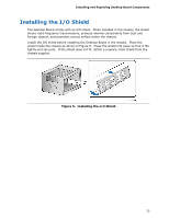
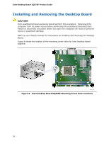
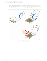
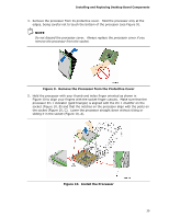
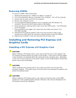
Intel Desktop Board DQ67EP Product Guide 6. Carefully lower the socket lever (Figure 11, A) while making sure that the front edge of the load plate slides under the shoulder screw cap as the lever is lowered. Latch the socket lever under the load plate tab (Figure 11, C, D). The socket cover (Figure 11, B) will pop off as shown. Figure 11. Secure the Load Plate in Place 7. Pick up the socket cover and remove it from the desktop board. NOTE Do not discard the socket cover; save it for possible future use. Always replace the socket cover if you remove the processor from the socket. 40
-
 1
1 -
2
-
3
-
4
-
5
-
6
-
7
-
8
-
9
-
10
-
11
-
12
-
13
-
14
-
15
-
16
-
17
-
18
-
19
-
20
-
21
-
22
-
23
-
24
-
25
-
26
-
27
-
28
-
29
-
30
-
31
-
32
-
33
-
34
-
 35
35 -
 36
36 -
 37
37 -
 38
38 -
 39
39 -
 40
40 -
 41
41 -
 42
42 -
 43
43 -
 44
44 -
 45
45 -
46
-
47
-
48
-
49
-
50
-
51
-
52
-
53
-
54
-
55
-
56
-
57
-
58
-
59
-
60
-
61
-
62
-
63
-
64
-
65
-
66
-
67
-
68
-
69
-
70
-
71
-
72
-
73
-
74
-
75
-
76
-
77
-
78
-
79
-
80
-
81
-
82
-
83
-
84
-
85
-
86
 |
 |
Intel Desktop Board DQ67EP Product Guide
40
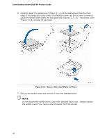
6.
Carefully lower the socket lever (Figure 11, A) while making sure that the front
edge of the load plate slides under the shoulder screw cap as the lever is lowered.
Latch the socket lever under the load plate tab (Figure 11, C, D).
The socket cover
(Figure 11, B) will pop off as shown.
Figure 11.
Secure the Load Plate in Place
7.
Pick up the socket cover and remove it from the desktop board.
NOTE
Do not discard the socket cover; save it for possible future use.
Always replace
the socket cover if you remove the processor from the socket.