Intel DQ67EP English Product Guide - Page 52
Front Panel USB 2.0 Headers, Front Panel Header, Table 8. Front Panel USB 2.0 Headers Signal Names
 |
View all Intel DQ67EP manuals
Add to My Manuals
Save this manual to your list of manuals |
Page 52 highlights
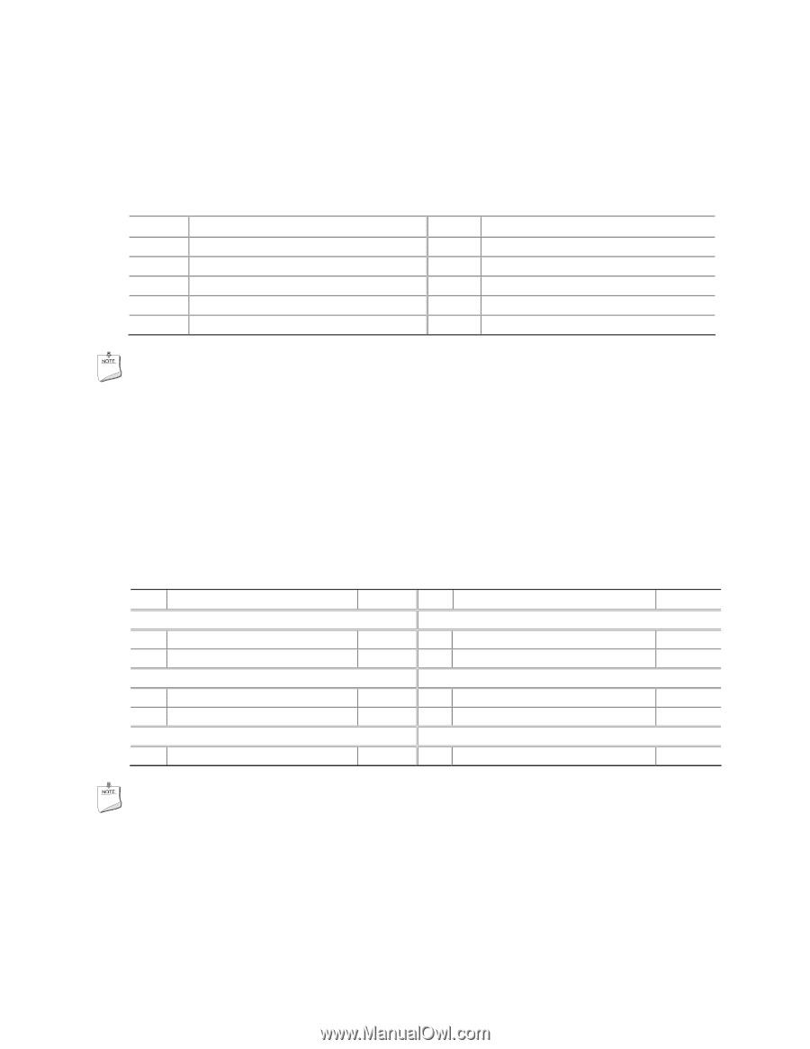
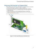
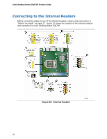
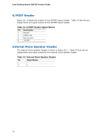
Intel Desktop Board DQ67EP Product Guide Front Panel USB 2.0 Headers Figure 20, C shows the location of the front panel USB 2.0 headers and Table 8 lists the pin assignments and signal names. Table 8. Front Panel USB 2.0 Headers Signal Names Pin Signal Name 1 Power (+5 V) 3 D- 5 D+ 7 Ground 9 Key Pin Signal Name 2 Power (+5 V) 4 D- 6 D+ 8 Ground 10 No Connection NOTE Computer systems that have an unshielded cable attached to a USB port might not meet FCC Class B requirements, even if no device or a low-speed USB device is attached to the cable. Use a shielded cable that meets the requirements for a full-speed USB device. Front Panel Header Figure 20, D shows the location of the front panel header. Table 9 lists the pin assignments and signal names for the front panel header. Table 9. Front Panel Header Signal Names Pin Description In/Out Pin Description Hard Disk Drive Activity LED Power LED 1 Hard disk LED pull-up to +5 V Out 2 Front panel LED+ 3 Hard disk active LED Out 4 Front panel LED- Reset Switch On/Off Switch 5 Ground 6 Power switch 7 Reset switch In 8 Ground Power Not Connected 9 Power Out 10 No pin In/Out Out Out In NOTE When connecting individual wires from your chassis front panel to the front panel header, be sure to observe the connection polarity. Positive wires are usually solid color and negative wires are usually white or striped. 52
-
 1
1 -
2
-
3
-
4
-
5
-
6
-
7
-
8
-
9
-
10
-
11
-
12
-
13
-
14
-
15
-
16
-
17
-
18
-
19
-
20
-
21
-
22
-
23
-
24
-
25
-
26
-
27
-
28
-
29
-
30
-
31
-
32
-
33
-
34
-
35
-
36
-
37
-
38
-
39
-
40
-
41
-
42
-
43
-
44
-
45
-
46
-
 47
47 -
 48
48 -
 49
49 -
 50
50 -
 51
51 -
 52
52 -
 53
53 -
 54
54 -
 55
55 -
 56
56 -
 57
57 -
58
-
59
-
60
-
61
-
62
-
63
-
64
-
65
-
66
-
67
-
68
-
69
-
70
-
71
-
72
-
73
-
74
-
75
-
76
-
77
-
78
-
79
-
80
-
81
-
82
-
83
-
84
-
85
-
86
 |
 |