Intel DX48BT2 Product Guide
Intel DX48BT2 - Desktop Board Extreme Series Motherboard Manual
 |
UPC - 735858199773
View all Intel DX48BT2 manuals
Add to My Manuals
Save this manual to your list of manuals |
Intel DX48BT2 manual content summary:
- Intel DX48BT2 | Product Guide - Page 1
Intel® Desktop Board DX48BT2 Product Guide Order Number: E27416-001 - Intel DX48BT2 | Product Guide - Page 2
at any time, without notice. Desktop Board DX48BT2 may contain design defects or errors known as errata which may cause the product to deviate from published specifications. Current characterized errata are available on request. Contact your local Intel sales office or your distributor to obtain - Intel DX48BT2 | Product Guide - Page 3
by Intel. Document Organization The chapters in this Product Guide are arranged as follows: 1 Desktop Board Features: a summary of product features 2 Installing and Replacing Desktop Board Components: instructions on how to install the Desktop Board and other hardware components 3 Updating the BIOS - Intel DX48BT2 | Product Guide - Page 4
Intel Desktop Board DX48BT2 Product Guide Terminology The table below gives descriptions of some common terms used in the product guide. Term Description GB Gigabyte (1,073,741,824 bytes) GHz Gigahertz (one billion hertz) KB Kilobyte (1024 bytes) MB Megabyte (1,048,576 bytes) Mb - Intel DX48BT2 | Product Guide - Page 5
1 Desktop Board Features Supported Operating Systems 10 Desktop Board Components 11 Processor ...13 Main Memory...14 Intel® X48 Express Chipset 15 Audio Subsystem 15 LAN Subsystem 16 USB 2.0 Support 17 Enhanced IDE Interface 17 Serial ATA...17 Legacy I/O ...17 Expandability...18 BIOS ...18 - Intel DX48BT2 | Product Guide - Page 6
Audio System 53 Connecting Chassis Fan and Power Supply Cables 54 Connecting Chassis Fan Cables 54 Connecting Power Supply Cables 55 Setting the BIOS Configuration Jumper 56 Clearing Passwords 57 Replacing the Battery 58 3 Updating the BIOS Updating the BIOS with the Intel® Express BIOS - Intel DX48BT2 | Product Guide - Page 7
22 4. Onboard Power Button 24 5. Location of the VR and CPU LEDs 25 6. Installing the I/O Shield 29 7. Desktop Board DX48BT2 Mounting Screw Hole Locations 30 8. Lift the Socket Lever 31 9. Lift the Load Plate 32 10. Remove the Protective Socket Cover 32 11. Remove the Processor from the - Intel DX48BT2 | Product Guide - Page 8
Intel Desktop Board DX48BT2 Product Guide 25. Connecting the IDE Cable 46 26. Connecting a Serial ATA Cable 47 27. Internal Headers and Connectors 48 28. Back Panel Audio Connectors 53 29. Location of the Chassis Fan Headers 54 30. Connecting Power Supply Cables 55 31. Location of the BIOS - Intel DX48BT2 | Product Guide - Page 9
describes the features of Intel® Desktop Board DX48BT2. Table 1 summarizes the major features of the Desktop Board. Table 1. Feature Summary Form Factor Processor Main Memory Chipset Graphics Audio Expansion Capabilities Legacy I/O Support Peripheral Interfaces RAID ATX (304.80 millimeters [12 - Intel DX48BT2 | Product Guide - Page 10
about Desktop Board DX48BT2, including the Technical Product Specification (TPS), BIOS updates, and device drivers, go to: http://support.intel.com/support/motherboards/desktop/ Supported Operating Systems The Desktop Board supports the following operating systems: • Microsoft Windows Vista - Intel DX48BT2 | Product Guide - Page 11
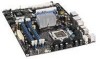
Desktop Board Features Desktop Board Components Figure 1 shows the approximate location of the major components on Desktop Board DX48BT2. Figure 1. Desktop Board DX48BT2 Components 11 - Intel DX48BT2 | Product Guide - Page 12
audio header PCI Express 2.0 x16 primary connector Rear chassis fan header (3-pin) MCH fan header (3-pin) Back panel connectors 12 V processor core voltage connector (2 x 4 pin) Processor socket Processor fan header (4-pin) DDR3 DIMM 0 sockets DDR3 DIMM 1 sockets IDE connector Main power connector - Intel DX48BT2 | Product Guide - Page 13
: • Desktop Board DX48BT2 http://www.intel.com/design/motherbd http://support.intel.com/support/motherboards/ desktop • Supported processors http://www.intel.com/go/findCPU • Audio software and utilities http://www.intel.com/design/motherbd • LAN software and drivers http://www.intel.com - Intel DX48BT2 | Product Guide - Page 14
Intel Desktop Board DX48BT2 Product Guide Main Memory NOTE To be fully compliant with all applicable Intel ® SDRAM memory specifications, the board should be populated with DIMMs that support the Serial Presence Detect (SPD) data structure. If your memory modules do not support SPD, you will see a - Intel DX48BT2 | Product Guide - Page 15
for more information about: • Audio drivers and utilities http://support.intel.com/support/motherboards/desktop/ • The location of the onboard audio headers, Figure 27 on page 48 • The signal names for the Intel High Definition Audio front panel header and the HD Audio Link header, page 49 • The - Intel DX48BT2 | Product Guide - Page 16
and drivers: http://support.intel.com/support/motherboards/desktop Two LEDs are built into the RJ-45 LAN connector located on the back panel (see Figure 2). These LEDs indicate the status of the LAN. Figure 2. LAN Connector LEDs Table 3 describes the LED states when the board is powered up - Intel DX48BT2 | Product Guide - Page 17
your system for RAID using Intel® Matrix Storage Technology see Chapter 4. Legacy I/O Desktop Board DX48BT2 includes an I/O controller that provides the following legacy I/O features: • Consumer Infrared (CIR) support • Low pin count (LPC) interface • Intelligent power management, including - Intel DX48BT2 | Product Guide - Page 18
Intel Desktop Board DX48BT2 Product Guide Expandability Desktop Board DX48BT2 provides the following expansion capability: • Two PCI Express 2.0 x16 ports • One PCI Express 1.1 x4 port (routed to a x16 connector) • Two PCI bus connectors BIOS The BIOS provides the Power-On Self-Test (POST), the BIOS - Intel DX48BT2 | Product Guide - Page 19
57. Hardware Management The hardware management features of Desktop Board DX48BT2 enable the board to be compatible with the Wired for Management (WfM) specification. The board has several hardware management features including the following: • Fan speed monitoring and control • Thermal and voltage - Intel DX48BT2 | Product Guide - Page 20
Intel Desktop Board DX48BT2 Product Guide Power Management Power management is implemented at several levels, including software support through the Advanced Configuration and Power Interface (ACPI) and the following hardware support: • Power connectors • Fan headers • LAN wake capabilities • - Intel DX48BT2 | Product Guide - Page 21
as needed. • All fan headers have a +12 V DC connection. The Desktop Board has a 4-pin processor fan header, one 4-pin and two 3-pin chassis fan headers, and one 3-pin MCH fan header. LAN Wake Capabilities CAUTION For LAN wake capabilities, the 5 V standby line for the power supply must be capable - Intel DX48BT2 | Product Guide - Page 22
Intel Desktop Board DX48BT2 Product Guide The Desktop Board supports the PCI Bus Power Management Interface Specification. Add-in cards that support this specification can participate in power management and can be used to wake the computer. +5 V Standby Power Indicator CAUTION If the AC power has - Intel DX48BT2 | Product Guide - Page 23
on standby current requirements for the Desktop Board, refer to the Technical Product Specification by going to the following link, finding the product, and selecting Product Documentation from the left-hand menu: http://support.intel.com/support/motherboards/desktop/ Wake from USB NOTE Wake from - Intel DX48BT2 | Product Guide - Page 24
Intel Desktop Board DX48BT2 Product Guide Onboard Power Button CAUTION Electrostatic discharge (ESD) can damage antistatic wrist strap and attaching it to a metal part of the computer chassis. A power button on the Desktop Board (see Figure 4) can be used to turn the computer on or off. This button - Intel DX48BT2 | Product Guide - Page 25
5, B) indicates an elevated temperature on the processor that could affect performance. Figure 5. Location of the VR and CPU LEDs Speaker A speaker is mounted on the Desktop Board. The speaker provides audible error code (beep code) information during the Power-On Self-Test (POST). Refer to Appendix - Intel DX48BT2 | Product Guide - Page 26
Intel Desktop Board DX48BT2 Product Guide Battery A battery on the Desktop Board keeps the values in CMOS RAM and the clock current when the computer is turned off. Go to page 58 for instructions on how to replace the battery. Real-Time Clock The Desktop Board has a time-of-day clock and 100-year - Intel DX48BT2 | Product Guide - Page 27
an MCH heat sink fan • Install and remove memory • Install and remove a PCI Express x16 card • Connect the IDE and Serial ATA cables • Connect to the internal headers and connectors • Connect to the audio system • Connect chassis fan and power supply cables • Set the BIOS configuration jumper - Intel DX48BT2 | Product Guide - Page 28
Intel Desktop Board DX48BT2 Product Guide Installation Precautions When you install and test the Intel Desktop Board, observe all warnings and cautions in the installation instructions. To avoid injury, be careful of: • Sharp pins on connectors • Sharp pins on printed circuit assemblies • Rough - Intel DX48BT2 | Product Guide - Page 29
Installing and Replacing Desktop Board Components Installing the I/O Shield The Desktop Board comes with an I/O shield. When installed in the chassis, the shield blocks radio frequency transmissions, protects internal components from dust and foreign objects, and promotes correct airflow within the - Intel DX48BT2 | Product Guide - Page 30
the power before you open the computer can result in personal injury or equipment damage. Refer to your chassis manual for instructions on installing and removing the Desktop Board. Figure 7 shows the location of the mounting screw holes for Desktop Board DX48BT2. Figure 7. Desktop Board DX48BT2 - Intel DX48BT2 | Product Guide - Page 31
and Replacing Desktop Board Components Installing and Removing a Processor Instructions on how to install the processor on the Desktop Board are given below. Installing a Processor CAUTION Before installing or removing a processor, make sure the AC power has been removed by unplugging the power cord - Intel DX48BT2 | Product Guide - Page 32
Intel Desktop Board DX48BT2 Product Guide 3. Lift the load plate (Figure 9, A). Do not touch the socket contacts (Figure 9, B). Figure 9. Lift the Load Plate 4. Remove the plastic protective socket cover from the load plate (Figure 10). Do not discard the protective socket cover. Always replace the - Intel DX48BT2 | Product Guide - Page 33
and Replacing Desktop Board Components 5. Remove the processor from the protective processor cover. Hold the processor only at the edges, being careful not to touch the bottom of the processor (see Figure 11). Do not discard the protective processor cover. Always replace the processor cover - Intel DX48BT2 | Product Guide - Page 34
Intel Desktop Board DX48BT2 Product Guide 7. Pressing down on the load plate (Figure 13, A), close and engage the socket lever (Figure 13, B). Figure 13. Close the Load Plate 34 - Intel DX48BT2 | Product Guide - Page 35
DX48BT2 has mounting holes for a processor fan heat sink. For instructions on how to attach the processor fan heat sink to the Desktop Board, refer to the boxed processor manual. Connecting the Processor Fan Heat Sink Cable Connect the processor fan heat sink cable to the 4-pin processor fan header - Intel DX48BT2 | Product Guide - Page 36
Intel Desktop Board DX48BT2 Product Guide Removing the Processor For instructions on how to remove the processor fan heat sink and processor, refer to the processor installation manual. Installing the ICH Heat Sink Decorative Cover (Optional) To install the ICH heat sink decorative cover, follow - Intel DX48BT2 | Product Guide - Page 37
x 20 mm, 12 V dc fan. You can use the board's 3-pin MCH fan header to supply power to the MCH fan. NOTE An MCH heat sink fan is not included with Desktop Board DX48BT2 and must be purchased separately. To install an MCH heat sink fan, follow these instructions: 1. Observe the precautions in "Before - Intel DX48BT2 | Product Guide - Page 38
Intel Desktop Board DX48BT2 Product Guide Installing and Removing Memory NOTE To be fully compliant with all applicable Intel SDRAM memory specifications, the board requires DIMMs that support the Serial Presence Detect (SPD) data structure. Desktop board DX48BT2 has four 240-pin DDR3 DIMM sockets - Intel DX48BT2 | Product Guide - Page 39
Installing and Replacing Desktop Board Components Figure 18. Dual Channel Memory Configuration with Four DIMMs Three DIMMs If you want to 1 of channel B (see Figure 19). Figure 19. Dual Channel Memory Configuration with Three DIMMs NOTE All other memory configurations will result in single channel - Intel DX48BT2 | Product Guide - Page 40
Intel Desktop Board DX48BT2 Product Guide Installing DIMMs To make sure you have the correct DIMM, place it on the illustration of the DDR3 DIMM in Figure 20. All the notches should match with the DDR3 DIMM. Figure 20. Use DDR3 DIMMs 40 - Intel DX48BT2 | Product Guide - Page 41
Installing and Replacing Desktop Board Components To install a DIMM, follow these steps: 1. Observe the precautions in "Before You Begin" on page 27. 2. Turn off all peripheral devices connected to the computer. Turn off the computer and disconnect the AC power cord. 3. Remove the computer's cover - Intel DX48BT2 | Product Guide - Page 42
Intel Desktop Board DX48BT2 Product Guide Removing DIMMs To remove a DIMM, follow these steps: 1. Observe the precautions in "Before You Begin" on page 27. 2. Turn off all peripheral devices connected to the computer. Turn off the computer. 3. Remove the AC power cord from the computer. 4. Remove - Intel DX48BT2 | Product Guide - Page 43
Replacing Desktop Board Components Installing and Removing a PCI Express x16 Card CAUTION When installing a PCI Express card on the Desktop Board, ensure that the card is fully seated in the PCI Express connector before you power protection of the power supply, certain Desktop Board components and/or - Intel DX48BT2 | Product Guide - Page 44
Intel Desktop Board DX48BT2 Product Guide Installing a PCI Express x16 Card Follow these instructions to install any PCI Express x16 card: 1. Observe the precautions in "Before You Begin" on page 27. 2. Place the card in a PCI Express x16 connector ( - Intel DX48BT2 | Product Guide - Page 45
Installing and Replacing Desktop Board Components Removing a PCI Express x16 Card Follow these instructions to remove a PCI Express x16 card from a or similar tool (Figure 24, B) in the notch. This will release the card from the connector (C). 4. Pull the card straight up. Figure 24. Removing a - Intel DX48BT2 | Product Guide - Page 46
Intel Desktop Board DX48BT2 Product Guide Connecting the IDE Cable The IDE cable can be used to connect two IDE drives to the Desktop Board. The cable supports the ATA-66/100 transfer protocol. Figure 25 shows the correct installation of the cable. NOTES ATA-66/100 compatible cables are backward - Intel DX48BT2 | Product Guide - Page 47
Installing and Replacing Desktop Board Components Connecting the Serial ATA (SATA) Cables SATA cables support the Serial ATA protocol. Each cable can be used to connect one internal SATA drive to the Desktop Board. For correct cable function: 1. Observe the precaution in "Before You Begin" on page - Intel DX48BT2 | Product Guide - Page 48
in "Before You Begin" on page 27. Figure 27 shows the location of the internal headers and connectors on Intel Desktop Board DX48BT2. Item Description A Front panel audio B HD Audio Link C Back panel CIR emitter (output) D Front panel CIR receiver (input) E Chassis intrusion Item - Intel DX48BT2 | Product Guide - Page 49
Installing and Replacing Desktop Board Components Front Panel Audio Header Figure 27, A shows the location of the front panel audio header. Table 4 shows the pin assignments and signal names for the front panel audio header. Table 4. Front Panel Audio Header Signal Names Pin Signal Name 1 PORT - Intel DX48BT2 | Product Guide - Page 50
Intel Desktop Board DX48BT2 Product Guide NOTE The Consumer IR option must be enabled in the system BIOS before it can function. Press at boot to enter the system BIOS, and go to Advanced > Peripheral Configuration > Enhanced Consumer IR, and set CIR Header Emitter (Output) Header Signal Names - Intel DX48BT2 | Product Guide - Page 51
Installing and Replacing Desktop Board Components IEEE 1394a Header Figure 27, F shows the location of the IEEE 1394a header. Table 9 shows the pin assignments and signal names for the IEEE 1394a header. Table 9. IEEE 1394a Header Signal Names Pin Signal Name 1 TPA1+ 3 Ground 5 TPA2+ 7 + - Intel DX48BT2 | Product Guide - Page 52
Intel Desktop Board DX48BT2 Product Guide Front Panel Header Figure 27, I shows the location of the front panel header. Table 11 shows the pin assignments and signal names for the front panel header. Table 11. Front Panel Header Signal Names Pin Description In/Out Pin Description Hard Drive - Intel DX48BT2 | Product Guide - Page 53
Installing and Replacing Desktop Board Components Connecting to the Flexible Audio System After installing the IDT* audio driver from the Intel® Express Installer DVD-ROM, the multi-channel audio feature can be enabled. Figure 28 shows the back panel audio connectors. The default connector - Intel DX48BT2 | Product Guide - Page 54
Intel Desktop Board DX48BT2 Product Guide Connecting Chassis Fan and Power Supply Cables Connecting Chassis Fan Cables Connect chassis fan cables to the 3-pin and 4-pin chassis fan headers on the Desktop Board. Figure 29 shows the location of the chassis fan headers. Figure 29. Location of the - Intel DX48BT2 | Product Guide - Page 55
or the system may not function properly. The 2 x 12 pin main power connector on the Desktop Board is backwards compatible with ATX12V power supplies with 2 x 10 connectors. Use of the 1 x 4 power connector is required with ATX12V power supplies when using PCI Express add-in cards that can consume up - Intel DX48BT2 | Product Guide - Page 56
® processor Extreme Edition or other Intel processor that is not running at its default settings. Doing so may result in damage to the Desktop Board. 3. Connect the 1 x 4 power supply cable to the 1 x 4 connector. 4. Connect the main power supply cable to the 2 x 12 pin connector. Setting the BIOS - Intel DX48BT2 | Product Guide - Page 57
Installing and Replacing Desktop Board Components Table 14. Jumper Settings for the BIOS Setup Program Modes Jumper Setting Mode Normal (default) (1-2) Description The BIOS uses the current configuration and passwords for booting. Configure (2-3) Recovery (None) After the Power-On Self-Test ( - Intel DX48BT2 | Product Guide - Page 58
Intel Desktop Board DX48BT2 Product Guide 12. To restore normal operation, place the jumper on pins 1-2 as shown below. 13. Replace the cover, plug in the computer, and turn on the computer. Replacing the Battery A coin-cell battery (CR2032) powers the real-time clock and CMOS memory. When the - Intel DX48BT2 | Product Guide - Page 59
Installing and Replacing Desktop Board Components VARO Räjähdysvaara, jos pariston tyyppi on väärä. Paristot on kierrätettävä, jos se on mahdollista. Käytetyt paristot on hävitettävä paikallisten ympäristömääräysten mukaisesti. VORSICHT - Intel DX48BT2 | Product Guide - Page 60
Intel Desktop Board DX48BT2 Product Guide VIGYÁZAT Ha a telepet nem a megfelelő típusú telepre cseréli, az felrobbanhat. A telepeket lehetőség szerint újra kell hasznosítani. A használt telepeket a helyi környezetvédelmi - Intel DX48BT2 | Product Guide - Page 61
Installing and Replacing Desktop Board Components POZOR Zamenjava baterije z baterijo drugačnega tipa lahko povzroči eksplozijo. Če je mogoče, baterije reciklirajte. Rabljene baterije zavrzite v skladu z lokalnimi okoljevarstvenimi predpisi. . UYARI Yanlış türde - Intel DX48BT2 | Product Guide - Page 62
Intel Desktop Board DX48BT2 Product Guide To replace the battery, follow these steps: 1. Observe the precautions in "Before You Begin" (see page 27). 2. Turn off all peripheral devices connected to the computer. Disconnect the computer's power cord from the AC power source (wall outlet or power - Intel DX48BT2 | Product Guide - Page 63
of the Intel® Flash Memory Update Utility and the ease of use of Windows-based installation wizards. To update the BIOS with the Intel Express BIOS Update utility: 1. Go to the Intel World Wide Web site: http://support.intel.com/support/motherboards/desktop/ 2. Navigate to the DX48BT2 page, click - Intel DX48BT2 | Product Guide - Page 64
Intel Flash Memory Update Utility You can obtain either of these files through your computer supplier or by navigating to the Desktop Board DX48BT2 page on the Intel World Wide Web site at: http://support.intel.com/support/motherboards/desktop Navigate to the DX48BT2 page, click "[view] Latest BIOS - Intel DX48BT2 | Product Guide - Page 65
Intel Desktop Board BIOS Upgrade CD-ROM" page, press any key to confirm the BIOS upgrade operation. 6. Wait for the BIOS upgrade process to complete. CAUTION DO NOT POWER DOWN YOUR COMPUTER before the update is complete. The update may take up to 5 minutes. Updating the BIOS with the Iflash Memory - Intel DX48BT2 | Product Guide - Page 66
. Due to BIOS size and recovery requirements, a CD-R with the .BIO file in the root directory will be required. Related Links: For more information about updating the Intel Desktop Board BIOS or recovering from a BIOS update failure, go to: http://support.intel.com/support/motherboards/desktop/sb/CS - Intel DX48BT2 | Product Guide - Page 67
system BIOS Setup by pressing after the Power-On-Self-Test (POST) memory tests begin. 3. Go to Advanced Drive Configuration Configure SATA as; ensure that RAID is selected. 4. Then save your settings by pressing . Creating Your RAID Set 1. Upon re-boot, you will see the following Intel - Intel DX48BT2 | Product Guide - Page 68
Intel Desktop Board DX48BT2 Product Guide Loading the Intel Matrix Storage Technology RAID Drivers and Software 1. Begin Windows Setup by booting from the Windows installation CD. 2. At the beginning of Windows Setup, press to install a third-party SCSI or RAID driver. When prompted, insert the - Intel DX48BT2 | Product Guide - Page 69
the Desktop Board's two back panel eSATA connectors. 2. Enter system BIOS Setup by pressing the key after the Power-On-Self-Test (POST) memory tests begin. 3. Go to Advanced Peripheral Configuration Secondary SATA Controller; ensure that RAID is selected. 4. Then save your settings by pressing - Intel DX48BT2 | Product Guide - Page 70
Intel Desktop Board DX48BT2 Product Guide 70 - Intel DX48BT2 | Product Guide - Page 71
Indicators Desktop Board DX48BT2 reports POST errors in two ways: • By sounding a beep code • By displaying an error message on the monitor BIOS Beep Codes The BIOS also issues a beep code (one long tone followed by two short tones) during POST if the video configuration fails (a faulty video card - Intel DX48BT2 | Product Guide - Page 72
Intel Desktop Board DX48BT2 Product Guide 72 - Intel DX48BT2 | Product Guide - Page 73
Desktop Board DX48BT2 complies with the safety standards stated in Table 17 when correctly installed in a compatible host system. Table 17. Safety Standards Regulation CSA/UL 60950-1, First Edition EN 60950-1:2006, Second Edition on this Desktop Board to provide instructions for replacing and - Intel DX48BT2 | Product Guide - Page 74
Intel Desktop Board DX48BT2 Product Guide European Union Declaration of Conformity Statement We, Intel Corporation, declare under our sole responsibility that the product Intel® Desktop Board DX48BT2 is in conformity with all applicable essential requirements necessary for CE marking, following the - Intel DX48BT2 | Product Guide - Page 75
consult http://www.intel.com/intel/other/ehs/product_ecology for the details of this program, including the scope of covered products, available locations, shipping instructions, terms and conditions, etc Intel Product Recycling Program http://www.intel.com/intel/other/ehs/product_ecology 75 - Intel DX48BT2 | Product Guide - Page 76
Intel Desktop Board DX48BT2 Product Guide Deutsch Als Teil von Intels Engagement für den Umweltschutz hat das Unternehmen das Intel Produkt-Recyclingprogramm implementiert, das Einzelhandelskunden von Intel , les instructions d'expédition, les conditions générales, etc. http://www.intel.com/in - Intel DX48BT2 | Product Guide - Page 77
produtos cobertos, os locais disponíveis, as instruções de envio, os termos e condições, etc. Russian Intel Intel (Product Recycling Program Intel http://www.intel.com/intel/other/ehs/product_ecology Türkçe Intel, çevre sorumluluğuna bağımlılığının bir parçası olarak, perakende tüketicilerin - Intel DX48BT2 | Product Guide - Page 78
Intel Desktop Board DX48BT2 Product Guide Lead-free 2LI/Pb-free 2LI Board The electronics industry is transitioning acceptable because of the RoHS "flip chip" or "die bump" interconnect exemption. Desktop Board DX48BT2 is a lead-free second level interconnect product. Table 18 shows the lead-free - Intel DX48BT2 | Product Guide - Page 79
and components in which the Pb concentration level in the Desktop Board substrate and the solder connections from the board to or the components (second-level interconnect) is to 0.01% or 100 ppm) by weight of homogeneous material. Desktop Board DX48BT2 complies with these restrictions. 79 - Intel DX48BT2 | Product Guide - Page 80
specific product marking and a selfdeclaration of the controlled substances contained in each product. Desktop Board DX48BT2 is will not leak or chemically deteriorate while in the product. The EFUP for Intel Desktop Boards has been determined to be 10 years. The EFUP for Desktop Board DX48BT2 - Intel DX48BT2 | Product Guide - Page 81
Regulatory Compliance The China MII stipulates that a material Self Declaration Table (SDT) must be included in a product's user documentation. The SDT for Desktop Board DX48BT2 is shown in Figure 33. Figure 33. Desktop Board DX48BT2 China RoHS Material Self Declaration Table 81 - Intel DX48BT2 | Product Guide - Page 82
Intel Desktop Board DX48BT2 Product Guide EMC Regulations Desktop Board DX48BT2 complies with the EMC regulations stated in Table 20 when correctly installed in a compatible host system. Table 20. EMC Regulations Regulation (Class B) FCC 47 CFR Part 15, Subpart B ICES-003 Issue 4 EN55022:2006 - Intel DX48BT2 | Product Guide - Page 83
. Pay close attention to the following when reading the installation instructions for the host chassis, power supply, and other modules: • Product certifications or lack of certifications • External I/O cable shielding and filtering • Mounting, grounding, and bonding requirements • Keying connectors - Intel DX48BT2 | Product Guide - Page 84
Intel Desktop Board DX48BT2 Product Guide Product Certifications Board-Level Certification Markings Desktop Board DX48BT2 has the product certification markings shown in Table 21. Table 21. Product Certification Markings Description UL joint US/Canada Recognized Component mark. Includes adjacent - Intel DX48BT2 | Product Guide - Page 85
Component Certifications Ensure that the chassis and certain components; such as the power supply, peripheral drives, wiring, and cables; are components certified for the country Industry Canada statement at the front of this product guide demonstrates compliance with Canadian EMC regulations. 85 - Intel DX48BT2 | Product Guide - Page 86
Intel Desktop Board DX48BT2 Product Guide 86
-
 1
1 -
 2
2 -
 3
3 -
 4
4 -
 5
5 -
 6
6 -
 7
7 -
8
-
9
-
10
-
11
-
12
-
13
-
14
-
15
-
16
-
17
-
18
-
19
-
20
-
21
-
22
-
23
-
24
-
25
-
26
-
27
-
28
-
29
-
30
-
31
-
32
-
33
-
34
-
35
-
36
-
37
-
38
-
39
-
40
-
41
-
42
-
43
-
44
-
45
-
46
-
47
-
48
-
49
-
50
-
51
-
52
-
53
-
54
-
55
-
56
-
57
-
58
-
59
-
60
-
61
-
62
-
63
-
64
-
65
-
66
-
67
-
68
-
69
-
70
-
71
-
72
-
73
-
74
-
75
-
76
-
77
-
78
-
79
-
80
-
81
-
82
-
83
-
84
-
85
-
86
 |
 |

Intel
®
Desktop Board DX48BT2
Product Guide
Order Number:
E
27416
-001