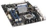
Intel DX48BT2 Product Guide - Page 8

Tables, Desktop Board DX48BT2 China RoHS Material Self Declaration Table - power supply

Page 8 highlights

Intel Desktop Board DX48BT2 Product Guide 25. Connecting the IDE Cable 46 26. Connecting a Serial ATA Cable 47 27. Internal Headers and Connectors 48 28. Back Panel Audio Connectors 53 29. Location of the Chassis Fan Headers 54 30. Connecting Power Supply Cables 55 31. Location of the BIOS Configuration Jumper Block 56 32. Removing the Battery 62 33. Desktop Board DX48BT2 China RoHS Material Self Declaration Table 81 Tables 1. Feature Summary 9 2. Desktop Board DX48BT2 Components 12 3. LAN Connector LEDs 16 4. Front Panel Audio Header Signal Names 49 5. HD Audio Link Header Signal Names 49 6. Front Panel CIR Receiver (Input) Header Signal Names 50 7. Back Panel CIR Header Emitter (Output) Header Signal Names 50 8. Chassis Intrusion Header Signal Names 50 9. IEEE 1394a Header Signal Names 51 10. USB 2.0 Header Signal Names 51 11. Front Panel Header Signal Names 52 12. Alternate Front Panel Power LED Header Signal Names 52 13. S/PDIF Connector Signal Names 52 14. Jumper Settings for the BIOS Setup Program Modes 57 15. Beep Codes 71 16. BIOS Error Messages 71 17. Safety Standards 73 18. Lead-Free Second Level Interconnect Marks 79 19. China RoHS Environmentally Friendly Use Period Mark 80 20. EMC Regulations 82 21. Product Certification Markings 84 viii

  • 1
  • 2
  • 3
  • 4
  • 5
  • 6
  • 7
  • 8
  • 9
  • 10
  • 11
  • 12
  • 13
  • 14
  • 15
  • 16
  • 17
  • 18
  • 19
  • 20
  • 21
  • 22
  • 23
  • 24
  • 25
  • 26
  • 27
  • 28
  • 29
  • 30
  • 31
  • 32
  • 33
  • 34
  • 35
  • 36
  • 37
  • 38
  • 39
  • 40
  • 41
  • 42
  • 43
  • 44
  • 45
  • 46
  • 47
  • 48
  • 49
  • 50
  • 51
  • 52
  • 53
  • 54
  • 55
  • 56
  • 57
  • 58
  • 59
  • 60
  • 61
  • 62
  • 63
  • 64
  • 65
  • 66
  • 67
  • 68
  • 69
  • 70
  • 71
  • 72
  • 73
  • 74
  • 75
  • 76
  • 77
  • 78
  • 79
  • 80
  • 81
  • 82
  • 83
  • 84
  • 85
  • 86

Intel Desktop Board DX48BT2 Product Guide
viii
25. Connecting the IDE Cable
..............................................................................
46
26. Connecting a Serial ATA Cable
........................................................................
47
27. Internal Headers and Connectors
....................................................................
48
28. Back Panel Audio Connectors
.........................................................................
53
29. Location of the Chassis Fan Headers
................................................................
54
30. Connecting Power Supply Cables
....................................................................
55
31. Location of the BIOS Configuration Jumper Block
..............................................
56
32. Removing the Battery
...................................................................................
62
33. Desktop Board DX48BT2 China RoHS Material Self Declaration Table
...................
81
Tables
1.
Feature Summary
..........................................................................................
9
2.
Desktop Board DX48BT2 Components
.............................................................
12
3.
LAN Connector LEDs
.....................................................................................
16
4.
Front Panel Audio Header Signal Names
...........................................................
49
5.
HD Audio Link Header Signal Names
...............................................................
49
6.
Front Panel CIR Receiver (Input) Header Signal Names
......................................
50
7.
Back Panel CIR Header Emitter (Output) Header Signal Names
...........................
50
8.
Chassis Intrusion Header Signal Names
...........................................................
50
9.
IEEE 1394a Header Signal Names
...................................................................
51
10.
USB 2.0 Header Signal Names
........................................................................
51
11.
Front Panel Header Signal Names
...................................................................
52
12.
Alternate Front Panel Power LED Header Signal Names
......................................
52
13.
S/PDIF Connector Signal Names
.....................................................................
52
14.
Jumper Settings for the BIOS Setup Program Modes
..........................................
57
15.
Beep Codes
.................................................................................................
71
16.
BIOS Error Messages
....................................................................................
71
17.
Safety Standards
..........................................................................................
73
18.
Lead-Free Second
Level Interconnect Marks
.....................................................
79
19.
China RoHS Environmentally Friendly Use Period Mark
.......................................
80
20.
EMC Regulations
...........................................................................................
82
21.
Product Certification Markings
........................................................................
84