Intel E6750 Design Guidelines - Page 101
D.5.3, Solder Process
 |
UPC - 735858194464
View all Intel E6750 manuals
Add to My Manuals
Save this manual to your list of manuals |
Page 101 highlights
Case Temperature Reference Metrology Figure 7-26. Positioning Solder on IHS D.5.3 23. Measure the resistance from the thermocouple end wires again using the DMM (refer to Section D.5.1.step 2) to ensure the bead is still properly contacting the IHS. Solder Process 24. Make sure the thermocouple that monitors the Solder Block temperature is positioned on the Heater block. Connect the thermocouple to a handheld meter to monitor the heater block temperature. 25. Verify the temperature of the Heater block station has reached 155 °C ±5 °C before you proceed. 26. Connect the thermocouple for the device being soldered to a second hand held meter to monitor IHS temperature during the solder process. Thermal and Mechanical Design Guidelines 101
-
 1
1 -
2
-
3
-
4
-
5
-
6
-
7
-
8
-
9
-
10
-
11
-
12
-
13
-
14
-
15
-
16
-
17
-
18
-
19
-
20
-
21
-
22
-
23
-
24
-
25
-
26
-
27
-
28
-
29
-
30
-
31
-
32
-
33
-
34
-
35
-
36
-
37
-
38
-
39
-
40
-
41
-
42
-
43
-
44
-
45
-
46
-
47
-
48
-
49
-
50
-
51
-
52
-
53
-
54
-
55
-
56
-
57
-
58
-
59
-
60
-
61
-
62
-
63
-
64
-
65
-
66
-
67
-
68
-
69
-
70
-
71
-
72
-
73
-
74
-
75
-
76
-
77
-
78
-
79
-
80
-
81
-
82
-
83
-
84
-
85
-
86
-
87
-
88
-
89
-
90
-
91
-
92
-
93
-
94
-
95
-
 96
96 -
 97
97 -
 98
98 -
 99
99 -
 100
100 -
 101
101 -
 102
102 -
 103
103 -
 104
104 -
 105
105 -
 106
106 -
107
-
108
-
109
-
110
-
111
-
112
-
113
-
114
-
115
-
116
-
117
-
118
-
119
-
120
-
121
-
122
-
123
-
124
-
125
-
126
-
127
-
128
-
129
-
130
-
131
-
132
-
133
-
134
-
135
-
136
-
137
-
138
-
139
-
140
-
141
-
142
-
143
-
144
-
145
-
146
-
147
-
148
 |
 |
Case Temperature Reference Metrology
Thermal and Mechanical Design Guidelines
101
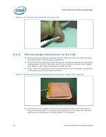
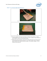
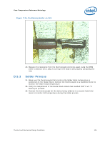
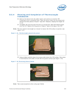
Figure 7-26. Positioning Solder on IHS
23. Measure the resistance from the thermocouple end wires again using the DMM
(refer to Section D.5.1.step 2) to ensure the bead is still properly contacting the
IHS.
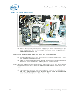
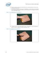
D.5.3
Solder Process
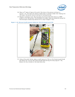
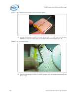
24. Make sure the thermocouple that monitors the Solder Block temperature is
positioned on the Heater block. Connect the thermocouple to a handheld meter to
monitor the heater block temperature.
25. Verify the temperature of the Heater block station has reached 155 °C ±5 °C
before you proceed.
26. Connect the thermocouple for the device being soldered to a second hand held
meter to monitor IHS temperature during the solder process.