Intel E6750 Design Guidelines - Page 74
Intel, QST Configuration and Tuning, Fan Hub Thermistor and Intel
 |
UPC - 735858194464
View all Intel E6750 manuals
Add to My Manuals
Save this manual to your list of manuals |
Page 74 highlights
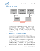
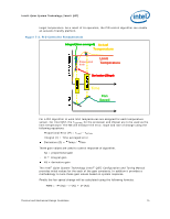
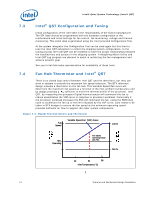
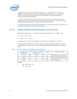
Intel® Quiet System Technology (Intel® QST) 7.3 Intel® QST Configuration and Tuning Initial configuration of the Intel QST is the responsibility of the board manufacturer. The SPI flash should be programmed with the hardware configuration of the motherboard and initial settings for fan control, fan monitoring, voltage and thermal monitoring. This initial data is generated using the Intel provided Configuration Tool. At the system integrator the Configuration Tool can be used again but this time to tune the Intel QST subsystem to reflect the shipping system configuration. In the tuning process the Intel QST can be modified to have the proper relationships between the installed fans and sensors in the shipping system. A Weighting Matrix Utility and Intel QST Log program are planned to assist in optimizing the fan management and achieve acoustic goal. See your Intel field sales representative for availability of these tools. 7.4 Fan Hub Thermistor and Intel® QST There is no closed loop control between Intel QST and the thermistor, but they can work in tandem to provide the maximum fan speed reduction. The BTX reference design includes a thermistor on the fan hub. This Variable Speed Fan curve will determine the maximum fan speed as a function of the inlet ambient temperature and by design provides a CA sufficient to meet the thermal profile of the processor. Intel QST, by measuring the processor Digital thermal sensor will command the fan to reduce speed below the VSF curve in response to processor workload. Conversely if the processor workload increases the FSC will command the fan using the PWM duty cycle to accelerate the fan up to the limit imposed by the VSF curve. Care needs to be taken in BTX designs to ensure the fan speed at the minimum operating speed provides sufficient air flow to support the other system components. Figure 7-5. Digital Thermal Sensor and Thermistor Full Speed Variable Speed Fan (VSF) Curve 100 % Min. Operating Fan Speed Operating Range with FSC Min % 30 34 38 Inlet Temperature (°C) § 74 Thermal and Mechanical Design Guidelines
-
 1
1 -
2
-
3
-
4
-
5
-
6
-
7
-
8
-
9
-
10
-
11
-
12
-
13
-
14
-
15
-
16
-
17
-
18
-
19
-
20
-
21
-
22
-
23
-
24
-
25
-
26
-
27
-
28
-
29
-
30
-
31
-
32
-
33
-
34
-
35
-
36
-
37
-
38
-
39
-
40
-
41
-
42
-
43
-
44
-
45
-
46
-
47
-
48
-
49
-
50
-
51
-
52
-
53
-
54
-
55
-
56
-
57
-
58
-
59
-
60
-
61
-
62
-
63
-
64
-
65
-
66
-
67
-
68
-
 69
69 -
 70
70 -
 71
71 -
 72
72 -
 73
73 -
 74
74 -
 75
75 -
 76
76 -
 77
77 -
 78
78 -
 79
79 -
80
-
81
-
82
-
83
-
84
-
85
-
86
-
87
-
88
-
89
-
90
-
91
-
92
-
93
-
94
-
95
-
96
-
97
-
98
-
99
-
100
-
101
-
102
-
103
-
104
-
105
-
106
-
107
-
108
-
109
-
110
-
111
-
112
-
113
-
114
-
115
-
116
-
117
-
118
-
119
-
120
-
121
-
122
-
123
-
124
-
125
-
126
-
127
-
128
-
129
-
130
-
131
-
132
-
133
-
134
-
135
-
136
-
137
-
138
-
139
-
140
-
141
-
142
-
143
-
144
-
145
-
146
-
147
-
148
 |
 |