Intel E6750 Design Guidelines - Page 76
A.2.2, Motherboard Deflection Metric Definition
 |
UPC - 735858194464
View all Intel E6750 manuals
Add to My Manuals
Save this manual to your list of manuals |
Page 76 highlights
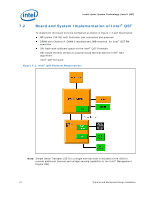
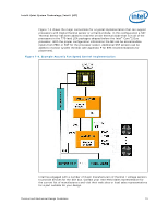
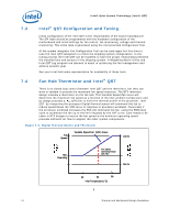
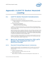
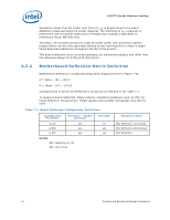
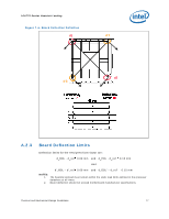
LGA775 Socket Heatsink Loading Simulation shows that the solder joint force (Faxial) is proportional to the board deflection measured along the socket diagonal. The matching of Faxial required to protect the LGA775 socket solder joint in temperature cycling is equivalent to matching a target MB deflection. Therefore, the heatsink preload for LGA775 socket solder joint protection against fatigue failure can be more generally defined as the load required to create a target board downward deflection throughout the life of the product. This board deflection metric provides guidance for mechanical designs that differ from the reference design for ATX//µATX form factor. A.2.2 Motherboard Deflection Metric Definition Motherboard deflection is measured along either diagonal (refer to Figure 7-6): d = dmax - (d1 + d2)/2 d' = dmax - (d'1 + d'2)/2 Configurations in which the deflection is measured are defined in the Table 7-1. To measure board deflection, follow industry standard procedures (such as IPC) for board deflection measurement. Height gauges and possibly dial gauges may also be used. Table 7-1. Board Deflection Configuration Definitions Configuration Parameter Processor + Socket load plate d_ref yes d_BOL yes d_EOL yes NOTES: BOL: Beginning of Life EOL: End of Life Heatsink no yes yes Parameter Name BOL deflection, no preload BOL deflection with preload EOL deflection 76 Thermal and Mechanical Design Guidelines
-
 1
1 -
2
-
3
-
4
-
5
-
6
-
7
-
8
-
9
-
10
-
11
-
12
-
13
-
14
-
15
-
16
-
17
-
18
-
19
-
20
-
21
-
22
-
23
-
24
-
25
-
26
-
27
-
28
-
29
-
30
-
31
-
32
-
33
-
34
-
35
-
36
-
37
-
38
-
39
-
40
-
41
-
42
-
43
-
44
-
45
-
46
-
47
-
48
-
49
-
50
-
51
-
52
-
53
-
54
-
55
-
56
-
57
-
58
-
59
-
60
-
61
-
62
-
63
-
64
-
65
-
66
-
67
-
68
-
69
-
70
-
 71
71 -
 72
72 -
 73
73 -
 74
74 -
 75
75 -
 76
76 -
 77
77 -
 78
78 -
 79
79 -
 80
80 -
 81
81 -
82
-
83
-
84
-
85
-
86
-
87
-
88
-
89
-
90
-
91
-
92
-
93
-
94
-
95
-
96
-
97
-
98
-
99
-
100
-
101
-
102
-
103
-
104
-
105
-
106
-
107
-
108
-
109
-
110
-
111
-
112
-
113
-
114
-
115
-
116
-
117
-
118
-
119
-
120
-
121
-
122
-
123
-
124
-
125
-
126
-
127
-
128
-
129
-
130
-
131
-
132
-
133
-
134
-
135
-
136
-
137
-
138
-
139
-
140
-
141
-
142
-
143
-
144
-
145
-
146
-
147
-
148
 |
 |