Intel E6750 Design Guidelines - Page 111
Board and System Implementation
 |
UPC - 735858194464
View all Intel E6750 manuals
Add to My Manuals
Save this manual to your list of manuals |
Page 111 highlights
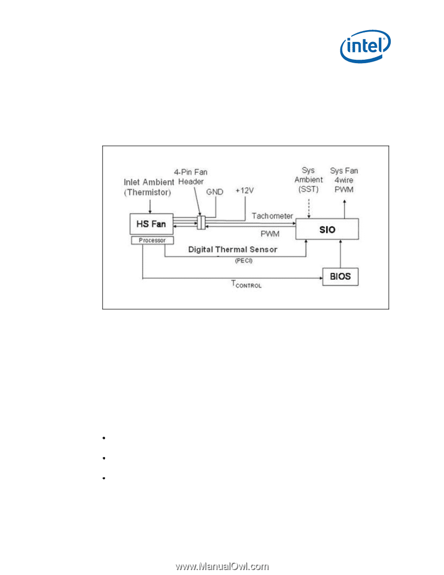
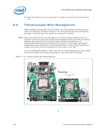
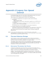
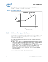
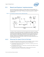
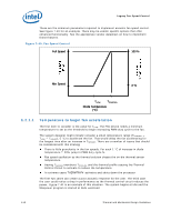
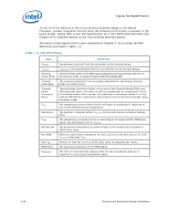
Legacy Fan Speed Control E.2 Board and System Implementation Once the thermal solution is defined, the system designer and board designer can define the fan speed control implementation. The first step is to select the appropriate fan speed controller (FSC). Figure 7-39 shows the major connections for a typical implementation. Figure 7-39. Example Fan Speed Control Implementation E.2.1 A number of major manufacturers have FSC components that include the necessary functionality to measure the temperature of the digital thermal sensor using the PECI interface and output a PWM signal. These components can be a discrete device or a super IO (SIO) with the functionality embedded. Intel has engaged with a number of major manufacturers of FSC components to provide devices that have a PECI host controller. Contact your Intel Field Sales representative for the current list of manufacturers and visit their web sites or contact your local sales representatives for a part suitable for your design. Choosing Fan Speed Control Settings Fan speed control algorithms allow the system thermal engineer a number of options to consider. The typical control settings that need to be considered are: The temperature when the fan will begin to accelerate in response to the on-die thermal sensor temperature (TLOW). The temperature where the fan is operating at full speed (100% PWM duty cycle). By specification this is TCONTROL. The minimum fan speed (PWM duty cycle). For any on-die thermal sensor temperature less than TLOW, the fan will run at this speed. Thermal and Mechanical Design Guidelines 111
-
 1
1 -
2
-
3
-
4
-
5
-
6
-
7
-
8
-
9
-
10
-
11
-
12
-
13
-
14
-
15
-
16
-
17
-
18
-
19
-
20
-
21
-
22
-
23
-
24
-
25
-
26
-
27
-
28
-
29
-
30
-
31
-
32
-
33
-
34
-
35
-
36
-
37
-
38
-
39
-
40
-
41
-
42
-
43
-
44
-
45
-
46
-
47
-
48
-
49
-
50
-
51
-
52
-
53
-
54
-
55
-
56
-
57
-
58
-
59
-
60
-
61
-
62
-
63
-
64
-
65
-
66
-
67
-
68
-
69
-
70
-
71
-
72
-
73
-
74
-
75
-
76
-
77
-
78
-
79
-
80
-
81
-
82
-
83
-
84
-
85
-
86
-
87
-
88
-
89
-
90
-
91
-
92
-
93
-
94
-
95
-
96
-
97
-
98
-
99
-
100
-
101
-
102
-
103
-
104
-
105
-
 106
106 -
 107
107 -
 108
108 -
 109
109 -
 110
110 -
 111
111 -
 112
112 -
 113
113 -
 114
114 -
 115
115 -
 116
116 -
117
-
118
-
119
-
120
-
121
-
122
-
123
-
124
-
125
-
126
-
127
-
128
-
129
-
130
-
131
-
132
-
133
-
134
-
135
-
136
-
137
-
138
-
139
-
140
-
141
-
142
-
143
-
144
-
145
-
146
-
147
-
148
 |
 |