Intel E6750 Design Guidelines - Page 66
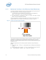
Core shoulder, traps clip in place
 |
UPC - 735858194464
View all Intel E6750 manuals
Add to My Manuals
Save this manual to your list of manuals |
Page 66 highlights
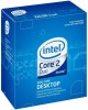
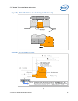
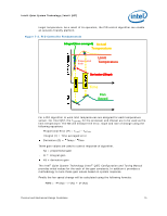
ATX Thermal/Mechanical Design Information 6.7.2 Mechanical Interface to the Reference Attach Mechanism The attach mechanism component from the reference design can be used by other 3rd party cooling solutions. The attach mechanism consists of: A metal attach clip that interfaces with the heatsink core, see Appendix H, Figure 7-55 and Figure 7-56 for the component drawings. Four plastic fasteners, see Appendix H, Figure 7-57, Figure 7-58, Figure 7-59 and Figure 7-60 for the component drawings. The clip is assembled to heatsink during copper core insertion, and is meant to be trapped between the core shoulder and the extrusion as shown in Figure 6-7. Figure 6-7. Reference Clip/Heatsink Assembly Clip Core shoulder traps clip in place The mechanical interface with the reference attach mechanism is defined in Figure 6-8 and Figure 6-9. Complying with the mechanical interface parameters is critical to generating a heatsink preload compliant with the minimum preload requirement given in Section 2.1.2.2. Additional requirements for the reference attach mechanism (clip and fasteners) include: Heatsink/fan mass 550 g (i.e., total assembly mass, including clip and fasteners < 595 g Whole assembly center of gravity 25.4 mm, measured from the top of the IHS Whole assembly = Heatsink + Fan + Attach clip + Fasteners 66 Thermal and Mechanical Design Guidelines
-
 1
1 -
2
-
3
-
4
-
5
-
6
-
7
-
8
-
9
-
10
-
11
-
12
-
13
-
14
-
15
-
16
-
17
-
18
-
19
-
20
-
21
-
22
-
23
-
24
-
25
-
26
-
27
-
28
-
29
-
30
-
31
-
32
-
33
-
34
-
35
-
36
-
37
-
38
-
39
-
40
-
41
-
42
-
43
-
44
-
45
-
46
-
47
-
48
-
49
-
50
-
51
-
52
-
53
-
54
-
55
-
56
-
57
-
58
-
59
-
60
-
 61
61 -
 62
62 -
 63
63 -
 64
64 -
 65
65 -
 66
66 -
 67
67 -
 68
68 -
 69
69 -
 70
70 -
 71
71 -
72
-
73
-
74
-
75
-
76
-
77
-
78
-
79
-
80
-
81
-
82
-
83
-
84
-
85
-
86
-
87
-
88
-
89
-
90
-
91
-
92
-
93
-
94
-
95
-
96
-
97
-
98
-
99
-
100
-
101
-
102
-
103
-
104
-
105
-
106
-
107
-
108
-
109
-
110
-
111
-
112
-
113
-
114
-
115
-
116
-
117
-
118
-
119
-
120
-
121
-
122
-
123
-
124
-
125
-
126
-
127
-
128
-
129
-
130
-
131
-
132
-
133
-
134
-
135
-
136
-
137
-
138
-
139
-
140
-
141
-
142
-
143
-
144
-
145
-
146
-
147
-
148
 |
 |