Intel SBX82 User Guide - Page 40
Attention
 |
UPC - 675900686984
View all Intel SBX82 manuals
Add to My Manuals
Save this manual to your list of manuals |
Page 40 highlights
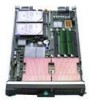
• The processor sockets in this server contain built-in termination for the processor bus; therefore, no terminator card is required if a processor socket 2 is empty. However, for proper airflow, this socket must contain a processor heat-sink filler, sometimes called a processor baffle. • The processor speeds are automatically set for this server; therefore, you do not have to set any processor frequency-selection jumpers or switches. The following illustration shows how to install the second processor on the system board for the blade server. Alignment marks Heat sink Microprocessor Heat sink filler Microprocessor locking lever Complete the following steps to install an additional processor: 1. Read the safety information beginning on page "Safety" on page vii and "Installation guidelines" on page 19. 2. Shut down the operating system, turn off the blade server, and remove the blade server from the SBCE unit (see "Installing and removing the blade server from the SBCE unit" on page 20 for instructions). 3. Carefully lay the blade server on a flat, non-conductive surface. 4. Open the blade server cover (see "Opening the blade server cover" on page 20 for instructions). 5. Remove the bezel assembly (see "Removing the blade server bezel assembly" on page 21 for instructions). 6. Locate the processor socket on the system board. 7. Remove the heat-sink filler. 8. Install the processor: a. Remove the protective cover, tape, or label from the surface of the processor socket, if one is present. b. Touch the non-conductive package containing the new processor to any unpainted metal surface on the blade server or any unpainted metal surface on any other grounded rack component in the rack you are installing the processor in for at least 2 seconds; then remove the processor from the package. Attention: Do not use any tools or sharp objects to lift the locking lever on the processor socket. Doing so might result in permanent damage to the system board. 26 Intel Server Compute Blade SBX82 Installation and User's Guide
-
 1
1 -
2
-
3
-
4
-
5
-
6
-
7
-
8
-
9
-
10
-
11
-
12
-
13
-
14
-
15
-
16
-
17
-
18
-
19
-
20
-
21
-
22
-
23
-
24
-
25
-
26
-
27
-
28
-
29
-
30
-
31
-
32
-
33
-
34
-
 35
35 -
 36
36 -
 37
37 -
 38
38 -
 39
39 -
 40
40 -
 41
41 -
 42
42 -
 43
43 -
 44
44 -
 45
45 -
46
-
47
-
48
-
49
-
50
-
51
-
52
-
53
-
54
-
55
-
56
-
57
-
58
-
59
-
60
-
61
-
62
-
63
-
64
-
65
-
66
-
67
-
68
-
69
-
70
-
71
-
72
-
73
-
74
-
75
-
76
-
77
-
78
-
79
-
80
-
81
-
82
-
83
-
84
-
85
-
86
-
87
-
88
 |
 |
