JVC TK-C215VP12U Instructions
JVC TK-C215VP12U - CCTV Camera - Vandal Manual
 |
UPC - 046838027482
View all JVC TK-C215VP12U manuals
Add to My Manuals
Save this manual to your list of manuals |
JVC TK-C215VP12U manual content summary:
- JVC TK-C215VP12U | Instructions - Page 1
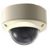
DOME CAMERA TK-C215VP4U/E TK-C215VP12U/E INSTRUCTIONS For Customer Use: Enter below the Serial No. which is located on the body. Retain this information for future reference. Model No. TK-C215VP4U/E,TK-C215VP12U/E Serial No. LST0519-001A - JVC TK-C215VP12U | Instructions - Page 2
service personnel under the following conditions: a. When the power cord or plug is damaged or frayed. b. If liquid has been spilled into the appliance. c. If the appliance has been exposed to rain or water. d. If the appliance does not operate normally by following the operating instructions - JVC TK-C215VP12U | Instructions - Page 3
the presence of important operating and maintenance (servicing) instructions in the literature accompanying the appliance. INFORMATION radio/TV technician for help. CAUTION CHANGES OR MODIFICATIONS NOT APPROVED BY JVC COULD VOID USER'S AUTHORITY TO OPERATE THE EQUIPMENT. THIS DEVICE COMPLIES WITH - JVC TK-C215VP12U | Instructions - Page 4
visit our web page www.jvc-europe.com to obtain information be made by a qualified service person and should conform to 70. ⅷ Any Mention in this manual of Alarm inputs have not been a secure location where it can support the mass of this unit. When the installation instructions correctly. Please - JVC TK-C215VP12U | Instructions - Page 5
This instruction manual covers total 4 different models in common as follows: TK-C215VP4U TK-C215VP4E TK-C215VP12U TK-C215VP12E In this manual, each model number is described without the last letter (U/E) which means the shipping destination. (U: NTSC, E: PAL) Only "U"models (TK-C215VP4U/TKC215VP12U - JVC TK-C215VP12U | Instructions - Page 6
of Contents 6 Precautions for proper use of this product ... 7 Name of Parts 9 Setting the Switches and the Lens (TK-C215VP4U/E 12 Setting the Switches and the Lens (TK-C215VP12U/E 14 Installation and Connection System Example 16 About Connection Cables 17 Video signal cables 17 DC 12 V or AC - JVC TK-C215VP12U | Instructions - Page 7
camera focus may change slightly after the zoom operation comes to a stop. This is due to the built-in lens performance and is not a malfunction. (TK-C215VP12U/E only) 7 - JVC TK-C215VP12U | Instructions - Page 8
turn off the power of the system to save energy. Ⅵ Note on consumable parts (TK-C215VP12U/E only) The following parts are consumable and should be replaced after a certain number of hours or a count of operations. The service lives given below are only typical values. They may vary depending on the - JVC TK-C215VP12U | Instructions - Page 9
. (A Pg. 21)(A Pg. 31) Note: ● To mount the camera using the electrical box, consult the dealer from which this product is purchased or any nearby JVC dealer. B Hole for Connecting Cable and Piping This is a hole for drawing out the connecting cable. This hole can also be used to mount directly - JVC TK-C215VP12U | Instructions - Page 10
to the following: U-type: Class 2 only E-type: Isolated power supply only ● For inquiries on the heater, consult your nearby JVC dealer. J Alarm signal cable (TK-C215VP12U/E only) Yellow (ALARM IN), Gray (ALARM GND). (A Pg. 18) K Protection Cover Upon connecting the video cable please protect the - JVC TK-C215VP12U | Instructions - Page 11
is used in the above illustration M Rotation Knob ( TK-C215VP4U/E only) Rotate the lens unit to adjust the for Heater Memo: ● When mounting the heater (sold separately: KA-ZH215), read the instruction manual of the heater carefully before mounting. U Camera Unit Fastening Clip ן2 This clip - JVC TK-C215VP12U | Instructions - Page 12
Introduction Setting the Switches and the Lens (TK-C215VP4U/E) Set the video setting switches on the camera unit before mounting it. To set the instructions on correcting white spots, see AWhite-spot correctionB (A Pg. 34). B [R/B,+/-] R/B,+/- adjustment button This button is pressed when manually - JVC TK-C215VP12U | Instructions - Page 13
type: 50 Hz only (Default setting: INT) 4. [WHT.BAL.] ATW/MANUAL selection switch. For selecting whether to adjust the white balance automatically or manually. When the setting is changed from manual to ATW, the setting values in the manual mode will be reset. The camera switches to the same mode as - JVC TK-C215VP12U | Instructions - Page 14
Introduction Setting the Switches and the Lens (TK-C215VP12U/E) Set the video setting switches on the camera unit corrected. For instructions on correcting white-spots, see AWhite-spot correctionB (A Pg. 34). F [R/B,+/-] R/B, +/- adjustment button This button is pressed when manually adjusting the - JVC TK-C215VP12U | Instructions - Page 15
type: 50 Hz only (Default setting: INT) 4. [WHT.BAL.] ATW/MANUAL selection switch. For selecting whether to adjust the white balance automatically or manually. When the setting is changed from manual to ATW, the setting values in the manual mode will be reset. The camera switches to the same mode as - JVC TK-C215VP12U | Instructions - Page 16
connecting the cables. ● Read through the "Instruction Manual" of the devices to be used carefully before connecting. TK-C215VP4U/E Coaxial Cable Power Cable TK-C215VP4U/E Coaxial Cable Power Cable TK-C215VP4U/E Coaxial Cable Power Cable TK-C215VP12U/E Coaxial Cable Power Cable Alarm Signal - JVC TK-C215VP12U | Instructions - Page 17
turn off the power of devices before connecting cables. To video Signal Cable To DC 12 V or AC 24 V Power Supply To Alarm Signal Cable ( TK-C215VP12U/E Only) Note: ● When mounting the heater (sold separately part number KA-ZH215), make sure to connect the power wire to an AC 24 V power supply - JVC TK-C215VP12U | Instructions - Page 18
Installation and Connection About Connection Cables (continued) Electrical Specifications of Alarm Input Terminals (TK-C215VP12U/E only) ● To prevent penetration of noise in the internal circuitry, apply a non-voltage contact signal to the ALARM input terminal. Never apply a voltage. ● Apply an - JVC TK-C215VP12U | Instructions - Page 19
of the camera unit, pay enough attention to the fall of each part. ⅷ When mounting the heater (sold separately: KA-ZH215), read the instruction manual of the heater carefully before mounting. step 1 K step 2 K step 3 K step 4 K step 5 K step 6 K step 7 Set the switches (A Pg. 20) Remove the dome - JVC TK-C215VP12U | Instructions - Page 20
Setting the switches Set the switches for video images. (APg. 12 eSetting the Switches and the Lens (TK-C215VP4U/E)f) (APg. 14 eSetting the Switches and the Lens (TK-C215VP12U/E)f) Inner 2 Dome Fall Prevention Wire Wrench (Supplied) Clip(x 3) 3 LL PHASE 1 2 O N2 3 4 4 5 6 WHT. 7 BAL - JVC TK-C215VP12U | Instructions - Page 21
mm (1 1/8 inch) Approx. 100 mm (37/8 inch) Coaxial Cable Power Supply Wire Alarm Signal Cable (AC 24 V only when heater is in use) *TK-C215VP12U/E only 1. Removing the camera unit from the base A Unfasten the 2 fastening screws from the camera unit using a screwdriver. B Press the 2 clips inwards to - JVC TK-C215VP12U | Instructions - Page 22
, make sure to connect it to an AC 24 V supply during use. 3. Connect the alarm cable. (TK-C215VP12U/E only)(A Pg. 18) 4. Binding the AC 24 V/DC 12 V power supply wires and alarm signal wires (TKC215VP12U/E only) with insulating tape Make sure to bind the connecting portions of AC 24 V/DC 12 V power - JVC TK-C215VP12U | Instructions - Page 23
material completely, water or vapor may enter the holes causing the lens and dome cover to fog. Make sure that these holes are completely filled. 3 *TK-C215VP4U/E is used in the above illustration 23 - JVC TK-C215VP12U | Instructions - Page 24
using the lug plate. Silica Gel Insertion Space Silica Gel Lug Plate *TK-C215VP4 is used in the above illustration Memo: ● During reconnection or re to replace the silica gel with a new one. ● Consult your nearby JVC's dealer on the replacement procedures. Serial number of part to be replaced: Use - JVC TK-C215VP12U | Instructions - Page 25
the pan fastening screw is loosened. Moving the lens unit without loosening the pan fastening screw may damage the lens unit. O N Rotation knob ( TK-C215VP4U/E only) : Always adjust the rotation by holding this knob. Memo: ● Panning/rotation of ±175 Њ is possible from each of the camera unit - JVC TK-C215VP12U | Instructions - Page 26
Level Adjustment Dial Focus Adjustment Button Zoom Adjustment Ring W T Focus Adjustment Ring N F Optical Axis *TK-C215VP4U/E is used in the above illustration ࡗTK-C215VP4U/E(A Pg. 26) ࡗTK-C215VP12U/E(A Pg. 28) Adjusting the angle of view Loosen the fastening screw for the zoom adjustment - JVC TK-C215VP12U | Instructions - Page 27
Adjusting the brightness Usually, adjustment of the brightness is not required. When this is necessary, adjust the iris level accordingly. To darken : Anti-clockwise direction (L side) To brighten : Clockwise direction (H side) Memo: ● Do not perform iris level adjustment within 30 seconds - JVC TK-C215VP12U | Instructions - Page 28
SELECT FAR IRIS WIDE TELE NEAR L [MEMORY] LEVEL H Installation and Connection Adjusting the video image (continued) Ⅵ TK-C215VP12U/E ● 2 types of angle of view may be selected for TK-C215VP12U/E. In general, set in a way such that the home position shoots a wide range and the alarm position - JVC TK-C215VP12U | Instructions - Page 29
LL PHASE RESET/[SPOT] H B R WHT.BAL. L [MEMORY] LEVEL IRIS TELE NEAR WIDE POSITION SELECT FAR POSITION ZOOM/FOCUS 8 7 6 5 4 4 3 2 2 ALARM 1 ⅷ Registering alarm position For registering the angle of view during monitoring when there is an alarm input. 3. 2.,4. 1.,5. 1. Check - JVC TK-C215VP12U | Instructions - Page 30
After setting is complete, mount the inner dome to the camera. 1. Mounting the inner dome Mount the inner dome to the 3 clips. Clip(x 3) Inner Dome *TK-C215VP4 is used in the above illustration Mounting the dome cover 1. Cleaning the dome cover Before mounting, remove any dust or dirt from the dome - JVC TK-C215VP12U | Instructions - Page 31
Note: ● Make sure that the dome cover is firmly fastened. Otherwise, the humidity level may rise, which may result in fogging and even falling of the cover. ● Ensure that the fall prevention wire of the dome cover is not caught in the space between the dome cover and base. Failing to do so may cause - JVC TK-C215VP12U | Instructions - Page 32
Installation and Connection Mounting the camera using the pipe Use the piping hole to mount the camera. Mounting the camera using the piping hole at the bottom surface of the base 1. Setting the switches (A Pg. 20) 2. Removing the camera unit from the base. (A Pg. 21 , step 1) 3. Mount the fall - JVC TK-C215VP12U | Instructions - Page 33
Mounting the camera using the piping hole at the side surface of the base If the camera cannot be mounted directly to the ceiling, mount it to the pipe using the piping hole at the side surface of the base. 1. Setting the switches (A Pg. 20) 2. Dismantle the camera unit from the base and mount the - JVC TK-C215VP12U | Instructions - Page 34
-C215VP4U/E RESET/[SPOT] [SPOT] button B R LL PHASE 1 2 3 4 5 6 7 8 O N2 4 WHT. BAL. Function selection switch 8 IRIS TELE L [MEMORY] LEVEL H Ⅵ TK-C215VP12U/E WHT.BAL. R B 6 7 8 LL PHASE RESET/[SPOT] [SPOT] button Function selection switch 8 1. Remove the dome cover. 2. Cover the - JVC TK-C215VP12U | Instructions - Page 35
35 - JVC TK-C215VP12U | Instructions - Page 36
, WIDE end) TK-C215VP12U Color mode : C215VP12E Color mode : 4.2 lx (Standard, AGC ON, 50 IRE, WIDE end) : 1.3 lx (Standard, AGC ON, 25 IRE, WIDE end) Black and White mode : 2.4 lx (Standard, AGC ON, 50 IRE, WIDE end) 0.8 lx (Standard, AGC ON, 25 IRE, WIDE end White balance : ATW/Manual - JVC TK-C215VP12U | Instructions - Page 37
) : -20 I to 40 I (-4 g to 104 g)(Recommended) Dustproof/Waterproof : IP 66 Mass TK-C215VP4 TK-C215VP12 : Approx. 1250 g : Approx. 1310 g Accessories U type: Instructions 1 Installation Precautions 1 Warranty Card 1 Service Information Card 1 Silica gel 1 Wrench 1 Template 1 E type - JVC TK-C215VP12U | Instructions - Page 38
Others Specifications (continued) Ⅵ Dimensional Outline Drawing [Unit: mm (inch)] 121(4-3/4) 113(4-1/2) Ǿ160(6-1/4 5(1/4) 42(1-5/8) G3/4-14 UNC screw for piping (bottom surface, side surface) 9 (3/8) 125(4-7/8) SR(523-1.7/8) Ǿ160(6-1/4) * Specifications and appearance of this unit and - JVC TK-C215VP12U | Instructions - Page 39
Focus chart 39 - JVC TK-C215VP12U | Instructions - Page 40
© 2006 Victor Company of Japan, Limited LST0519-001A TK-C215VP4U/E TK-C215VP12U/E DOME CAMERA
-
 1
1 -
 2
2 -
 3
3 -
 4
4 -
 5
5 -
 6
6 -
 7
7 -
8
-
9
-
10
-
11
-
12
-
13
-
14
-
15
-
16
-
17
-
18
-
19
-
20
-
21
-
22
-
23
-
24
-
25
-
26
-
27
-
28
-
29
-
30
-
31
-
32
-
33
-
34
-
35
-
36
-
37
-
38
-
39
-
40
 |
 |
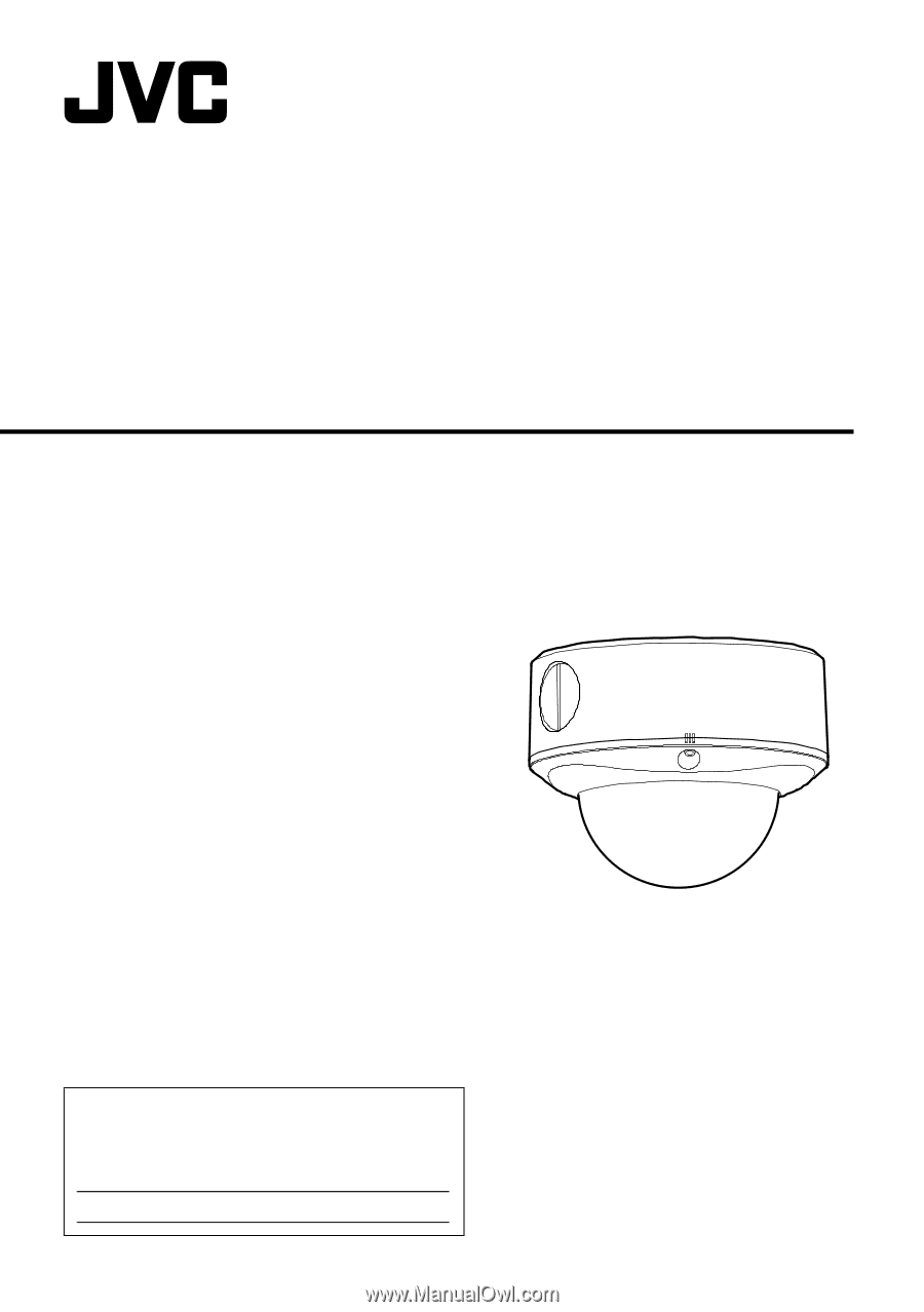
DOME CAMERA
TK-C215VP4U/E
TK-C215VP12U/E
INSTRUCTIONS
For Customer Use:
Enter below the Serial No. which is located on the
body. Retain this information for future reference.
Model No.
TK-C215VP4U/E,TK-C215VP12U/E
Serial No.
LST0519-001A