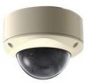
JVC TK-C215VP12U Instructions - Page 11
Camera Interior, Rotation Knob TK-C215VP4U/E only
 |
UPC - 046838027482
View all JVC TK-C215VP12U manuals
Add to My Manuals
Save this manual to your list of manuals |
Page 11 highlights
Camera (Interior) M N O P Q R S T Lens (A next page) Y X W V U *TK-C215VP4U/E is used in the above illustration M Rotation Knob ( TK-C215VP4U/E only) Rotate the lens unit to adjust the inclination of the image. (A Pg. 25) N Rotation Center Mark (A Pg. 25) O Fall Prevention Wire Use this to connect the base G to the dome cover D. P Camera Unit Fastening Screw ן2 Use this to fasten the camera body R to the base G. To remove (A Pg. 21) Q [MONITOR]Monitor Terminal (RCA Jack) (A Pg. 25) R Camera Unit S Connector for Power Supply of Heater This is a power connector for use when the heater (sold separately: KA-ZH215) is mounted. T Space for Heater Memo: ● When mounting the heater (sold separately: KA-ZH215), read the instruction manual of the heater carefully before mounting. U Camera Unit Fastening Clip ן2 This clip is used for fastening the camera unit to the base. When removing the base, press toward the direction indicated by the arrow to release. (A Pg. 21) V Tilt Fastening Screw Upon adjusting the angle of view, tighten the screw to ensure that camera's angle of view does not go out of alignment when it is used at a location with strong vibration. (A Pg. 25) W Shooting Direction Mark Install the camera by aligning the shooting direction with the arrow mark. X Lug Plate This plate is used for fastening the silica gel. (A Pg. 24) Y Space for Silica Gel (A Pg. 24) 11
-
 1
1 -
2
-
3
-
4
-
5
-
 6
6 -
 7
7 -
 8
8 -
 9
9 -
 10
10 -
 11
11 -
 12
12 -
 13
13 -
 14
14 -
 15
15 -
 16
16 -
17
-
18
-
19
-
20
-
21
-
22
-
23
-
24
-
25
-
26
-
27
-
28
-
29
-
30
-
31
-
32
-
33
-
34
-
35
-
36
-
37
-
38
-
39
-
40
 |
 |
