Kenmore 4104 Installation Instructions - Page 1
Kenmore 4104 - Elite 30 in. Slide-In Dual Fuel Range Manual
 |
View all Kenmore 4104 manuals
Add to My Manuals
Save this manual to your list of manuals |
Page 1 highlights
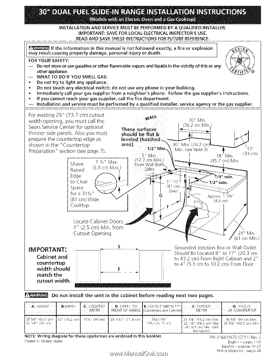
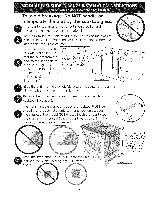
iNSTALLATiON AND SERVICE MUST BE PERFORMED BY A QUALIFIED iNSTALLER. IMPORTANT: SAVE FOR LOCAL ELECTRICALINSPECTOR'S USE. READ AND SAVE THESE INSTRUCTIONS FOR FUTURE REFERENCE. if the information in this manual is not followed exactly, a fire or explosion may result causing property damage, personal injury or death. FOR YOUR SAFETY: -- Do not store or use gasoline or other flammable vapors and liquids in the vicinity of this or any other appliance. m WHAT TO DO IF YOU SMELL GAS: Q Do not try to light any appliance. Q Do not touch any electrkal switch; do not use any phone in your building. Q Immediately call your gas supplier from a neighbor's phone. Follow the gas supplier's instructions. Q If you cannot reach your gas supplier, call the fire department. Installation and service must be performed by a qualified installer, service agency or the gas supplier. For existing 29" (73.7 cm) cutout width opening, you must call the Sears Service Center for optional thinner side panels. Also you must prepare the countertop edge as shown in the "Countertop Preparation" section (see page 7). These surfaces should be flat & laerveeal)e. d (hatched_ 112" Mi 5" Vlin. Shave Raised 1 1/2" Max (3.8 cm Max Sides Edge to Clear Space fora 31Y2" (81 cm) Wide Cooktop. 30" Min. (76.2 cm Min. 30" Min. (76.2 18" Min. (45.7 cm) Min. it (33 cm) IM PORTANT: Cabinet and countertop width should match the cutout width. Locate Cabinet Doors 1" (2.5 cm) Min. from Cutout Opening. 24" Min. I (61 cm Min.) Grounded Jonction Box or Wall Outlet Should Be Located 8" to 17" (20.3 cm to 43.2 cm) From Right Cabinet and 2" to 4" (5.1 cm to 10.2 cm) From Floor. i Do not install the unit in the cabinet before reading next two pages. A. HE!GHT I B.WIDTH. (:,COOKFOp I ! WIDTH [:);DEPTH TO E: CUTOUT W!DTH *** . FRONT OF RANGE (C0untert0p and Cabine! I:.CUTOUT DEPTH G:HEIGHT . OF COUNTERTOP 35 5/8" (90.5cm)36 5/8" (93 cm) 30" (76,2 cm) 311/2 '' (80cm) 28 5/16" (71,9 cm) 30_+1/16" (76,2_+0,15 cm) NOTE:Wiring diagram for these appliances are enclosed in this booklet. Printed in United States 21 3/4" (55,2 cm) Min. 22 1/8" (56,2 cm) Max 24" (61 cm) Min. with backguard 36 5/8" (93cm) Max. 35 5/8" (90.5 cm) Min. P/N 318201670 (0711) Rev. English- pages 1-13 Espahol- p_iginas 14-27 Wiring Diagrams - pages 28
-
 1
1 -
 2
2 -
 3
3 -
 4
4 -
 5
5 -
 6
6 -
 7
7 -
8
-
9
-
10
-
11
-
12
-
13
-
14
-
15
-
16
-
17
-
18
-
19
-
20
-
21
-
22
-
23
-
24
-
25
-
26
-
27
-
28
 |
 |