Kenwood VR-510 User Manual - Page 5
Names and functions of parts, Display, Standby mode
 |
View all Kenwood VR-510 manuals
Add to My Manuals
Save this manual to your list of manuals |
Page 5 highlights
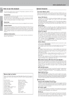
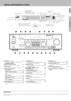
Preparation Names and functions of parts Frequency display, Input display, PRO LOGIC 5 Preset channel display, indicator Speaker indicator Surround mode display AUTO SOUND indicator DIGITAL indicator Band indicators S.DIRECT indicator AUTO indicator CLIP indicator MUTE indicator SP A B TI.VOL C L I P MUTE RDS EON PTY TP TA NEWS L CR LFE SW SL S SR FM AUTO SOUND DIGITAL AUTO AM PRO LOGIC S.DIRECT MEMO MHz 3 STEREO MONITOR ST. kHz DOWNMIX DSP TUNED MEMO. indicator ST. indicator TUNED indicator DOWNMIX indicator MONITOR indicator Speaker selection indicators Input channel indicators Output channel indicators Display DSP indicator 3 STEREO indicator STEREO indicator STANDBY POWER ON/STANDBY PHONES AUDIO-VIDEO SURROUND RECEIVER VR-510 A SPEAKERS B MULTI CONTROL DOLBY DTS DIGITAL THX DSP MODE SET UP INPUT MODE DIMMER MONITOR SOUND LISTEN MODE SOURCE DIRECT BAND AUTO MEMORY INPUT SELECTOR VOLUME CONTROL DOWN UP S-VIDEO V AV AUX L - AUDIO - R 1 POWER ( ) key ™ Use to switch the power ON/STANDBY. STANDBY indicator 2 MULTI CONTROL knob ™ Use to control a variety of settings. 3 SET UP key ™ Use to select the speakers' settings etc. 4 Surround indicators DTS indicator ¤ Lights when the receiver is in the DTS mode. DOLBY DIGITAL indicator ¤ Lights when the receiver is in the Dolby Digital mode. THX indicator ∞ Lights when the receiver is in the THX mode. DSP MODE indicator ¤ Lights when the receiver is in the DSP mode. CS 5.1 indicator ¤ Lights when the receiver is in the CS 5.1 mode. 5 INPUT MODE key 7 Use to switch between the digital and analog inputs. 6 DIMMER key Use to adjust the brightness of the display.fi Use to select the REC MODE. § 7 MONITOR key § Use to monitor the source that is connected to the MONITOR jack. 8 VOLUME CONTROL knob ¢ 9 PHONES jack ∞ Use for headphone listening. 0 SPEAKERS A/B keys ¢ Use to turn the A/B speakers ON/OFF. ! SOUND key ∞ Use to adjust the sound quality and ambience effects. @ BAND key ¶ Use to select the broadcast band. # AUTO Use to change "TAPE" indication to "MD".¢ Use to select the auto tuning mode. ¶ $ LISTEN MODE key › Use to select the listening mode. % MEMORY key ¶ Use to store radio stations in the preset memory. ^ SOURCE DIRECT key ∞ Use to pass the source material direct to the amplifier. & INPUT SELECTOR knob ¢ Use to select the input sources. * AV AUX (S VIDEO, V, AUDIO L/R) jacks * Standby mode When standby indicator is lit, this receiver is in standby mode and consumes a small amount of current for back-up. This system can be switched on using remote control.
-
 1
1 -
 2
2 -
 3
3 -
 4
4 -
 5
5 -
 6
6 -
 7
7 -
 8
8 -
 9
9 -
 10
10 -
 11
11 -
12
-
13
-
14
-
15
-
16
-
17
-
18
-
19
-
20
-
21
-
22
-
23
-
24
-
25
-
26
-
27
-
28
-
29
-
30
-
31
-
32
-
33
-
34
-
35
-
36
-
37
-
38
-
39
-
40
-
41
-
42
-
43
-
44
-
45
-
46
-
47
-
48
-
49
-
50
-
51
-
52
 |
 |
