LG FLATRON Service Manual - Page 16
Adjustment Instruction - tv manual
 |
View all LG FLATRON manuals
Add to My Manuals
Save this manual to your list of manuals |
Page 16 highlights
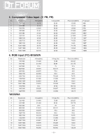
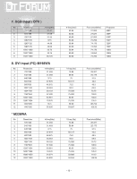
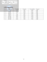
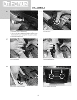
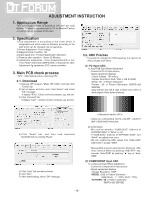
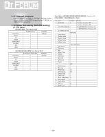
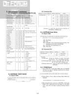
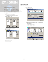
ADJUSTMENT INSTRUCTION 1. Application Range This specification sheet is applied to 19"/ 20"/ 22" LCD Monitor TV which is manufactured in TV (or Monitor) Factory or is produced on the basis of this data. 2. Specification 1) The adjustment is according to the order which is designated and which must be followed, according to the plan which can be changed only on agreeing. 2) Power Adjustment : Free Voltage 3) Magnetic Field Condition : Nil. 4) Input signal Unit : Product Specification Standard 5) Reserve after operation : Above 30 Minutes 6) Adjustment equipments : Color Analyzer(CA-210 or CA- 110), Pattern Generator (MSPG-925L or Equivalent), DDC Adjustment Jig equipment, SVC remote controller 3. Main PCB check process * APC - After Manual-Insult, executing APC 3.1. Download 1) Execute ISP program "Mstar ISP Utility" and then click "Config" tab. 2) Set as below, and then click "Auto Detect" and check "OK" message. If display "Error", Check connect computer, jig, and set. 3) Click "Connect" tab. If display "Can't ", Check connect computer, jig, and set. 3.2. ADC Process * If a scaler IC changed for PCB repairing, it is need to do ADC process at all times. (1) PC input ADC 1) Auto RGB Gain/Offset Adjustment - Convert to PC in Input-source - Signal equipment displays Output Voltage : 700 mVp-p Impress Resolution XGA (1024 x 768 @ 60Hz) Model : 60 in Pattern Generator Pattern : 29 in Pattern Generator (MSPG-925 SERISE) [gray pattern that left & right is black and center is white signal (Refer below picture)]. 4) Click "Read" tab, and then load download file(XXXX.bin) by clicking "Read". 5) Click "Auto" tab and set as below 6) click "Run". 7) After downloading, check "OK" message. - Adjust by commanding AUTO_COLOR _ADJUST (0xF1) 0x00 0x02 instruction. 2) Confirmation - We confirm whether "0x8B,0x8C" address of EEPROM "0xB4" is "0xAA" or not. - If "0x8B,0x8C" address of EEPROM "0xB4" isn't "0xAA", we adjust once more. - We can confirm the ADC values from "0x00~0x05" addresses in a page "0xB4" * Manual ADC process using Service Remocon. After enter Service Mode by pushing "INSTART" key, execute "Auto-RGB" by pushing " " key at "AutoRGB". (2) COMPONENT input ADC 1) Component Gain/Offset Adjustment - Convert to Component in Input-source - Signal equipment displays Impress Resolution 480P MODEL : 212 in Pattern Generator (480p Mode, Y : 100%, Pb/Pr : 75%) PATTERN : 08 in Pattern Generator (MSPG-925 SERISE) - 16 -
-
 1
1 -
2
-
3
-
4
-
5
-
6
-
7
-
8
-
9
-
10
-
 11
11 -
 12
12 -
 13
13 -
 14
14 -
 15
15 -
 16
16 -
 17
17 -
 18
18 -
 19
19 -
 20
20 -
 21
21 -
22
-
23
-
24
-
25
-
26
-
27
-
28
-
29
-
30
-
31
-
32
-
33
-
34
-
35
-
36
-
37
-
38
-
39
-
40
-
41
-
42
-
43
-
44
-
45
-
46
-
47
-
48
-
49
-
50
-
51
-
52
-
53
-
54
-
55
 |
 |
