LG FLATRON Service Manual - Page 30
Description Of Block Diagram
 |
View all LG FLATRON manuals
Add to My Manuals
Save this manual to your list of manuals |
Page 30 highlights
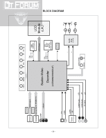
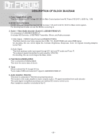
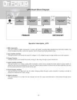
DESCRIPTION OF BLOCK DIAGRAM 1. Power Supply Block (LIPS) This Block Generates DC Voltage (5V,15V) to Main Control system from AC Power (100-240 V, 50/60 Hz, 1.0A) 2. DC/DC Converter block DC/DC Converter convert the input 5V,15V to proper 1.8V,2.5V,3.3V,5V,10.5V for Main control system. For shooting heat trouble, we use the DC/DC converting IC 3. Scaler + Video/Audio decorder (Scaler IC, LGE9689/9789AD-LF) It is composed of LGE9689/9789AD-LF. It includes AD Converter, LVDS/TMDS Transmitter, Micom, and Audio processor. 1) Video Signal - CVBS/S-Video/Component/RGB/DVI(TMDS) This Block Selects input Video signals (like CVBS, Y/C, SCART RGB) and output RGB signal. On decoding, We can control signal like Contrast, Brightness, Sharpness, Color, tint signals including Adaptive Comb Filter. 2) Audio Signal This block analyzes audio input signal through A/V Jack and PC audio and Tuner IF. The analyzed signals transmitted to audio amplifier (YDA138) On decoding, We can control signal like Bass, treble. 4. Flash Memory(MX25L4005A) This is composed of MX25L4005A. This store the source data of micom. 5. Tuner Micom controls this IC through IIC line. Tuner makes CVBS and transmits IF signal to LGE9689/9789AD-LF. 6. Audio Amplifier (YDA138) This block is composed of YDA138 and peripheral device. The function of the audio amplifier is that to amplify audio L / R signal transmitted from audio decoder. The audio signal is amplified according to pre-defined DC volume control curve. Also, headphone amplifier is included at this IC. - 30 -
-
 1
1 -
2
-
3
-
4
-
5
-
6
-
7
-
8
-
9
-
10
-
11
-
12
-
13
-
14
-
15
-
16
-
17
-
18
-
19
-
20
-
21
-
22
-
23
-
24
-
 25
25 -
 26
26 -
 27
27 -
 28
28 -
 29
29 -
 30
30 -
 31
31 -
 32
32 -
 33
33 -
 34
34 -
 35
35 -
36
-
37
-
38
-
39
-
40
-
41
-
42
-
43
-
44
-
45
-
46
-
47
-
48
-
49
-
50
-
51
-
52
-
53
-
54
-
55
 |
 |