LG FLATRON Service Manual - Page 20
Adjustment Command
 |
View all LG FLATRON manuals
Add to My Manuals
Save this manual to your list of manuals |
Page 20 highlights
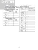
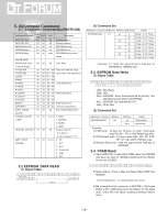
5. Adjustment Command 5.1. Adjustment Commands(LENGTH=84) Adjustment Contents CMD (hex) ADR VAL Description FACTORY ON E0 00 00 Factory mode on FACTORY OFF E2 00 00 Factory mode off EEPROM ALL INIT. E4 00 00 EEPROM All clear EEPROM Read E7 00 00 EEPROM Read EEPROM Write E8 00 data EEPROM Write by some values COLOR SAVE (R/G/B cutoff, Drive, EB 00 00 Color Save Contrast, Bright) H POSITION 20 00 00 - 100 They have different range V POSITION 30 00 00 - 100 each mode, FOS Adjustment CLOCK 90 00 00 - 100 PHASE 92 00 00 - 100 R DRIVE 16 00 00 - FF Drive adjustment G DRIVE 18 00 00 - FF B DRIVE 1A 00 00 - FF R CUTOFF 80 00 00 - 7F Offset adjustment G CUTOFF 82 00 00 - 7F B CUTOFF 84 00 00 - 7F BRIGHT 10 00 00 - 3F Bright adjustment CONTRAST 12 00 00 - 64 Luminance adjustment AUTO_COLOR_ F1 00 02 Auto COLOR Adjustment ADJUST CHANGE_COLOR F2 00 0,1,2,3 0: COOL _TEMP 1: NORMAL 2: WARM 3: USER FACTORY_DEFAULT F3 00 00 Factory mode off & II_SW is "1" & Input change to " TV" AUTO_INPUT F4 00 0,1,2,4 0 : TV CHANGE 1 : AV1 2 : AV2 3 : Component 4 : RGB 5 : DVI 5.2 EEPROM DATA READ (1) Signal Table Delay 100ms 128 Bytes (2) Command Set Adjustment contents CMD(hex) ADH(hex) ADL(hex) Details EEPROM READ E7 A0 0 0-Page 0~7F Read 80 0-Page 80~FF Read A2 0 1-Page 0~7F Read 80 1-Page 80~FF Read A4 0 2-Page 0~7F Read 80 2-Page 80~FF Read A6 0 3-Page 0~7F Read 80 3-Page 80~FF Read * Purpose : To read the appointment Address of E2PROM by 128(80h)-byte 5.3. E2PROM Data Write (1) Signal Table LEN : 84h+Bytes CMD : 8Eh ADH : E2PROM Slave Address(A0,A2,A4,A6,A8), Not 00h(Reserved by BufferToEEPROM) ADL : E2PROM Sub Address(00~FF) Data : Write data (2) Command Set Adjustment contents CMD(hex) EEPROM WRITE E8 ADH(hex) 94 84+n Details 16-Byte Write n-byte Write * Purpose 1) EDID write : 16-byte by 16-byte, 8 order (128-byte) write(TO "00 - 7F" of "EEPROM Page A4"). 2) FOS Default write : 16-mode data (HFh, HFl, VF, STD, HP, VP, Clk, ClkPh, PhFine) write. 3) Random Data write : write the appointment Address of E2PROM. 5.4. VRAM Read 1) Send CMD(70h) to read Video RAM value from MICOM And save its value to 128-Bytes Buffer(Common Buffer for the use of EDID) 2) Delay 500ms ( Time to Wait and Read Video RAM from MICOM) 3) Be transmitted the contents of MICOM's 128-bytes Buffer to PC. (128th Data is the CheckSum of 127-bytes data : That's OK if the value of adding 128-bytes Data is Zero) - 20 -
-
 1
1 -
2
-
3
-
4
-
5
-
6
-
7
-
8
-
9
-
10
-
11
-
12
-
13
-
14
-
 15
15 -
 16
16 -
 17
17 -
 18
18 -
 19
19 -
 20
20 -
 21
21 -
 22
22 -
 23
23 -
 24
24 -
 25
25 -
26
-
27
-
28
-
29
-
30
-
31
-
32
-
33
-
34
-
35
-
36
-
37
-
38
-
39
-
40
-
41
-
42
-
43
-
44
-
45
-
46
-
47
-
48
-
49
-
50
-
51
-
52
-
53
-
54
-
55
 |
 |
