LG FLATRON Service Manual - Page 31
LIPS Board Block Diagram - driver
 |
View all LG FLATRON manuals
Add to My Manuals
Save this manual to your list of manuals |
Page 31 highlights
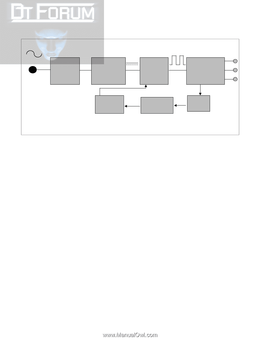
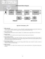
LIPS Board Block Diagram 50 ~ 60Hz LINE 100 ~ 240V EMI COMPONENTS INPUT RECTIFIER AND FILTER HVDC ENERGY TRANSFER 100KHz 15V OUTPUT RECTIFIER AND FILTER 5V GND PWM CONTROL CIRCUIT PRIMARY PHOTO -COUPLER ISOLATION SIGNAL COLLENT- ION SECONDARY Operation description_LIPS 1. EMI components. This part contains of EMI components to comply with global marketing EMI standards like FCC,VCCI CISPR, the circuit included a line-filter, across line capacitor and of course the primary protection fuse. 2. Input rectifier and filter. This part function is for transfer the input AC voltage to a DC voltage through a bridge rectifier and a bulk capacitor. 3. Energy Transfer. This part function is for transfer the primary energy to secondary through a power transformer. 4. Output rectifier and filter. This part function is to make a pulse width modulation control and to provide the driver signal to power switch, to adjust the duty cycle during different AC input and output loading condition to achieve the dcoutput stabilized, and also the over power protection is also monitor by this part. 5. Photo-Coupler isolation. This part function is to feed back the DC output changing status through a photo transistor to primary controller to achieve the stabilized DC output voltage. 6. Signal collection. This part function is to collect the any change from the DC output and feed back to the primary through photo transistor. - 31 -
-
 1
1 -
2
-
3
-
4
-
5
-
6
-
7
-
8
-
9
-
10
-
11
-
12
-
13
-
14
-
15
-
16
-
17
-
18
-
19
-
20
-
21
-
22
-
23
-
24
-
25
-
 26
26 -
 27
27 -
 28
28 -
 29
29 -
 30
30 -
 31
31 -
 32
32 -
 33
33 -
 34
34 -
 35
35 -
 36
36 -
37
-
38
-
39
-
40
-
41
-
42
-
43
-
44
-
45
-
46
-
47
-
48
-
49
-
50
-
51
-
52
-
53
-
54
-
55
 |
 |