LG KE600 Service Manual
LG KE600 - LG Cell Phone Manual
 |
View all LG KE600 manuals
Add to My Manuals
Save this manual to your list of manuals |
LG KE600 manual content summary:
- LG KE600 | Service Manual - Page 1
Service Manual Model : KE600 Service Manual KE600 Date: October, 2006 / Issue 1.0 - LG KE600 | Service Manual - Page 2
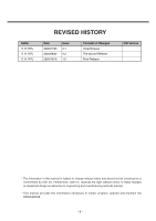
Changes Initial Release The second Release Final Release S/W Version * The information in this manual is subject to change without notice and should not be construed as a commitment methods warrant. * This manual provides the information necessary to install, program, operate and maintain the - LG KE600 | Service Manual - Page 3
-4- - LG KE600 | Service Manual - Page 4
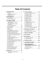
trouble 96 5.12 MicroSD trouble 98 5.13 Bluetooth trouble 99 5.14 FM Radio trouble 101 5.13 RF PART TROUBLESHOOTING ......103 6. Download & S/W upgrade 116 6.1 S/W download setup 116 6.2 Download program user guide 117 7. CIRCUIT DIAGRAM 121 8. PCB LAYOUT 127 9. RF Calibration 133 9.1 Test - LG KE600 | Service Manual - Page 5
-6- - LG KE600 | Service Manual - Page 6
steps to maintain telephone service. D. Maintenance Limitations Maintenance limitations on the KE600/KE608 must be performed only at the LGE or its authorized agents. The user may not make any changes and/or repairs expect as specifically noted in this manual. Therefore, note that unauthorized - LG KE600 | Service Manual - Page 7
provide information such as the following to the end user. F. Pictures The pictures in this manual are for illustrative purposes only; your actual hardware may look slightly different. G. Interference and Attenuation An KE600/KE608 may interfere with sensitive laboratory equipment, medical equipment - LG KE600 | Service Manual - Page 8
DCS dBm DSP EEPROM EGPRS EL ESD FPCB GMSK GPIB GPRS GSM IPUI IF LCD LDO LED Automatic Power Control Baseband Bit Error Ratio Constant Current - Constant Voltage Bus General Packet Radio Service Global System for Mobile Communications International Portable User Identity Intermediate Frequency Liquid - LG KE600 | Service Manual - Page 9
LGE OPLL PAM PCB PGA PLL PSTN RF RLR RMS RTC SAW SIM SLR SRAM STMR TA TDD TDMA UART VCO VCTCXO WAP 8PSK LG Electronics Offset Phase Locked Loop Power Amplifier Module Printed Circuit Board Programmable Gain Amplifier Phase Locked Loop Public Switched Telephone Network Radio Frequency Receiving - LG KE600 | Service Manual - Page 10
Phone Jack PC Synchronization Speech coding Data and Fax Vibrator Buzzer Voice Recoding C-Mic Receiver Travel Adapter Options Feature Li-Poly, 950mAh Battery Key, MP3 Key, Internal Type 12pin multi port Headset jack with Remote controller Yes HR/EFR/FR/AMR Yes Yes No Yes Yes Yes Yes Bluetooth hands- - LG KE600 | Service Manual - Page 11
2. PERFORMANCE 2.2 Technical specification Item Description 1 Frequency Band 2 Phase Error 3 Frequency Error 4 Power Level Specification GSM900 TX: 890 + 0.2 x n MHz RX: 935 + 0.2 x n MHz ( n = 1 ~ 124 ) EGSM TX: 890 + 0.2 x (n-1024) MHz RX: 935 + 0.2 x (n-1024) MHz ( n = 975 ~ 1023 ) - LG KE600 | Service Manual - Page 12
PERFORMANCE Item Description Output RF Spectrum 5 (due to modulation) Output RF Spectrum 6 (due to switching transient) Specification GSM900/EGSM Offset from Carrier (kHz). 100 200 250 400 600~ - LG KE600 | Service Manual - Page 13
Error Ratio 9 Rx Level Report accuracy 10 SLR 11 Sending Response 12 RLR 13 Receiving Response Specification DCS1800/PCS1900 Offset from Carrier (kHz). Max. (dBm) 400 -22 600 -24 1,200 -24 1,800 -27 Conduction, Emission Status GSM900/EGSM BER (Class II) < 2.439% @-102dBm DCS1800 - LG KE600 | Service Manual - Page 14
Display Specification 13 Battery Capacity 950mA):240 min GSM900/Lvl 12(Battery mode. 3. Broadcast set off. 4. Signal strength display set at 3 level above. 5. Backlight of phone set off. At least 65 dB under below conditions: 1. Ringer set as ringer. 2. Test distance set as 50 cm Fast Charge : < 600 - LG KE600 | Service Manual - Page 15
Specification Battery Bar Number Voltage( 0.05V) 4 3.86V~4.2V 3 3.75V~3.85V 2 3.75V~3.69V 1 3.69V~3.58V 0 3.58V~ 3.58V↓ 0.05V (Call) 3.50V↓ 0.05V (Standby) 3.35 0.05 V Li-ion Battery Standard Voltage = 3.7 V Battery full charge voltage = 4.2 V Capacity: 950mAh Switching-mode charger - LG KE600 | Service Manual - Page 16
Specification (Option: KE608 is not serviced for "EDGE mode") Item Description 1 RMS EVM 2 Peak EVM 3 95th Percentile EVM 4 Origin Offset Suppression 5 Power Level 6 Output RF Spectrum (due to modulation) Specification -54 600~ - LG KE600 | Service Manual - Page 17
to modulation) 7 Output RF Spectrum (due to switching transient) Specification DCS1800, PCS1900 Offset from carrier(kHz) 100 200 250 400 600~ - LG KE600 | Service Manual - Page 18
3. TECHNICAL BRIEF 3. TECHNICAL BRIEF Baseband circuit 3.1 KE600 / KE608 Component Block diagram. Figure 1 KE600/KE608 Hardware architecture KE600/KE608 is composed with 3 different PCB part such as main PCB, sub PCB and FPCB. - 19 - - LG KE600 | Service Manual - Page 19
3. TECHNICAL BRIEF The functional component arrangement is mentioned below diagram. Figure 2 KE600/KE608 Functional block diagram - 20 - - LG KE600 | Service Manual - Page 20
such as camera, software MIDI, MP3 sound. It is designed as a single chip solution, integrating the digital and mixed signal portions of the base band in 0.13um, 1.5V technology. The chip will fully support the FR, EFR, HR and AMR-NB vocoding.S-GOLD2TM support multi-slot operation modes HSCSD (up to - LG KE600 | Service Manual - Page 21
-filter with B*T=0.3 - EDGE Modulator: 8PSK-modulation with linearized GMSK-Pulse-Filter - Hardware accelerators for equalizer and channel decoding. - Incremental Redundancy memory for EDGE class 12 support - A5/1, A5/2, A5/3 Cipher unit - GEA1, GEA2, GEA3 Cipher Unit to - LG KE600 | Service Manual - Page 22
- Advanced static and dynamic power management features including TDMA-Frame synchronous low power mode and enhanced CPU modes(idle and sleep modes) - Pulse Number Modulation output for Automatic Frequency Correction(AFC) - Serial RF Control interface: support of direct conversion RF - A Universal - LG KE600 | Service Manual - Page 23
KE600/KE608 have two UART Drivers as follow : - USART1 : Hardware Flow Control / SW upgrade / Calibration - USART2 : SW debug trace. Table 3 USART Interface Spec block operates charging process and other related process by reading battery voltage and other analog values. Table 4 S-Gold2 ADC channel - LG KE600 | Service Manual - Page 24
/KE608 is using as follows except dedicated to SIM and Memory. KE600/KE608 GPIO(General Purpose Input/Output) Map, describing application, I/O state, and enable level, is shown in below table. Table 5 S-Gold2 GPIO pin Map Port function - LG KE600 | Service Manual - Page 25
& BLUETOOTH Camera DATA[0] Camera DATA[1] Camera DATA[2] Camera DATA[3] Camera DATA[4] Camera DATA[5] Camera DATA[6] Camera DATA[7] Camera pixel clock Camera H sync Camera V sync Camera main clock Camera power down( active high) Camera reset LCD data[0] LCD data[1] LCD data[2] LCD data[3] LCD data - LG KE600 | Service Manual - Page 26
indicator LED control TransFlash card power enable(active High) LCD Reset For Remote Control Headset For SM-Power, FM Radio, Audio AMP " SM-Power interrupt SIM CARD I/O SIM CARD CLOCK SIM CARD RESET Not Connected For T-Flash " " For Bluetooth " USB End of charging detect(High: EOC, Low: charging - LG KE600 | Service Manual - Page 27
VMICN BAT_TEMP RF_TEMP JACK_TYPE I_MONITOR REMOTE_ADC TDO TDI TMS TCK TRSTn RTCK - 28 - For Bluetooth " " For T-Flash " " For Receiver " For Speaker For Speaker For Mic " For Headset Mic " For Mic " Battery temperature detect RF Power amp reference temperature detect For 18Pin Cable Type Detect HW - LG KE600 | Service Manual - Page 28
3. TECHNICAL BRIEF ETM TRIG_IN MON1 MON2 TRACESYNC TRACECLK PIPESTAT[2] PIPESTAT[1] PIPESTAT[0] TRACEPKT[0] TRACEPKT[1] TRACEPKT[2] TRACEPKT[3] TRACEPKT[4] TRACEPKT[5] TRACEPKT[6] TRACEPKT[7] Data bus EBU_AD[0] EBU_AD[1] EBU_AD[2] EBU_AD[3] EBU_AD[4] EBU_AD[5] EBU_AD[6] EBU_AD[7] EBU_AD[8] EBU_AD - LG KE600 | Service Manual - Page 29
[16] Address bus[17] Address bus[18] Address bus[19] Address bus[20] Address bus[21] Address bus[22] Address bus[23] Address bus[24] Flash ROM chip select SDRAM Chip select Not used Not used - LG KE600 | Service Manual - Page 30
PA_BAND ANT_SW1 ANT_SW2 ANT_SW3 MODE KP_OUT(4) AU_PWR_EN LCD BACKLIGHT JACK_DETECT _FM_RESET AF_PWR_EN turn on Vibrator enable(High: enable, Low:disable) RF band select RF FEM control signal 1 RF FEM control signal 2 RF FEM control signal 3 For RF Key pad Audio amp power enable( active high) LCD - LG KE600 | Service Manual - Page 31
CC1CC1IO RTC_OUT VCXO_EN DSP DSPIN0 GPIO_62 GPIO_63 _RESET TRIG_OUT RTC_OUT VCXO_EN _BT_RESET Not Use _SIM_EN Sleep crystal 32.768KHz Sleep crystal 32.768KHz Baseband processor reset For JTAG & ETM Interface Wake up signal to alarm (High; wake up, Low: Power off) 26MHz clock enable - LG KE600 | Service Manual - Page 32
Control for charging Li-Ion/Polymer batteries under software control • Pre-charge current generator with selectable current level • RTC regulator with ultra-low quiescent current • USB interface support for peripheral and mini-host mode • Backlight LEDs driver with current selection and PWM dimming - LG KE600 | Service Manual - Page 33
DC/DC converter makes up to 40 % reduction of battery current for smart phone functions (e.g. organizer functions, games, MP3 decoding) possible. - SDBB has high efficiency up to 95% and also a power save mode. - Memory Interface is directly supported by the SDBB - SDBB can also act as main supply - LG KE600 | Service Manual - Page 34
for USB host VBUS supply voltage SM-POWER fully supports LED and Vibra Motor functionality - no external components needed - driver for backlight LEDs adjustable in steps up to 140mA and with soft turn on and off by PWM dimming - two driver outputs for single LEDs for pre-charge indication and - LG KE600 | Service Manual - Page 35
Memory & for LDO RF transceiver DSP in BBP ARM core in BBP Peripherals SIM card Peripherals SD card Analog block in BBP RTC block & Backup battery RF IC RF IC BT IC(Blue moon USB I/F Figure 5 Power domain block diagram of - LG KE600 | Service Manual - Page 36
3. TECHNICAL BRIEF RTC_OUT VCHS PWRON USB_PU VBUS_USB R202 220K R204 470K PWRON VBAT VBACKUP SPOWER_INT VCH_CTL PMRSTn R203 4.7K 49 GND 1V8_MEM 3V1_USB 1V5_RF VBAT FB201 L201 10uH C213 C214 0.1u 22u C215 22u C216 2.2u C217 2.2u C218 2.2u 1 2 VCHS 3 VBATS 4 VRFC ON 5 VDDPW 6 SW 7 - LG KE600 | Service Manual - Page 37
function for charging of Li-Ion or Li-Ion-Polymer batteries. Either a 1-cell Li-Ion or Li-Ion-Polymer battery with 4.1, 4.2 or 4.4 Volts may be used. Figure 7 Battery Block Indication 1. Charging method : CC-CV 2. Charger detect voltage : 4.0V 3. Charging time : 3h 4. Charging current : 600mA 5. CV - LG KE600 | Service Manual - Page 38
Power ON/OFF KE600/KE608 Power State : Defined 3cases as follow ] Power-ON : Power key detect ( SM-Power's ON port ] Power-ON-charging : Charger detect. ] -0.8 ~ Vbat-0.3) the above-mentioned bit won't be set. To support Remote power on function for factory mass production, applied an analog switch - LG KE600 | Service Manual - Page 39
Remote power on and End-key power on circuit 3.5. SIM interface KE600/KE608 supports 1.8V & 3V plug in SIM, SIM interface scheme is shown SIM card reference clock SIM_RST : SIM card Async /sync reset SIM_IO : SIM card bidirectional reset 2V85_SIM S SI1305-E3 G Q301 D SIM_ENn SIM_IO C340 22p - LG KE600 | Service Manual - Page 40
memory with LPSDRAM stacked device family offers multiple high-performance solutions. The Sibley flash die is manufactured on 90 nm process technology. It delivers 108 MHz synchronous burst and page-mode read rates with supports multi-partitioning with Read-While-Write (RWW) or Read-While-Erase (RWE - LG KE600 | Service Manual - Page 41
3. TECHNICAL BRIEF 3.7. LCD Display LCD module include: - LCD : 240 x 320 262K Colors TFT LCD - Backlight : 3 piece of white LED illumination LCD module is connected to sub board thru 35 pins connector. LCD FPC Interface Spec: Table 7 LCD FPC Interface Spec. Pin No. 1 2 3 4 5 6 7 8 9 10 11 12 13 - LG KE600 | Service Manual - Page 42
9T) SOCKET R106 0 KEY-JOG MODULE 20 PIN CONNECTOR ENBY0016601 KP_IN0 KP_IN1 KP_IN2 KP_IN3 KP_IN4 KP_OUT3 KP_OUT4 END_KEY VBAT END END R102 C101 0 NA MP3 OK R103 C102 0 NA SEND SNED R112 0 C103 NA KP_OUT3 SLIDE KEYPAD ARRAY Figure 12 SUB PCB part Jog-key matrix KP_IN1 KP_IN0 R404 - LG KE600 | Service Manual - Page 43
located on the MAIN PCB, Jog key for menu navigation, Power on (End key), MP3 hot key and Send key is on the SUB PCB, are connected via 50pin board to of the SM-POWER LED drivers is shown in below Figure14. (SLED1, SLED2 port are not used in the KE600.KE608) Figure 14 Keypad Back-light LEDs - - LG KE600 | Service Manual - Page 44
05.09.05 JOG LED ANODE AND CATHODE FOR 4 LEDs SLIDE_KEY_BACKLIGHT R123 R124 12 R131 12 2.7K 123 654 JOG_LED_ANODE JOG_LED_CATHODE Q101 EMX18 KEYPAD BACKLIGHT DRIVER R132 36 R125 R127 R128 150 LD101 TWH104-HS C107 0.1u KEYPAD BACKLIGHT BLUE LED LD103 150 TWH104-HS 150 LD104 TWH104-HS - LG KE600 | Service Manual - Page 45
3. TECHNICAL BRIEF 3.10. LCD back light illumination Employed the AAT2807 is a dual charge pump designed to support both the white LED backlight and flash applications for systems operating with lithium-ion/polymer batteries. The backlight charge pump is capable of driving up to three LEDs at a - LG KE600 | Service Manual - Page 46
3. TECHNICAL BRIEF Figure 19 S2Cwire EN/SET port control method Table 8. Charge pump IC LCD part current setting table - 47 - - LG KE600 | Service Manual - Page 47
TRACESYNC Figure 21 JTAG & ETM(Embedded Trace Module) interface connector In case of KE600/KE608 mass production, the JTAG & ETM interface connector will not be mount on board. That is only for developing and software debugging purpose.( It will not be mounted on mass production PCB) - 48 - - LG KE600 | Service Manual - Page 48
3. TECHNICAL BRIEF 3.13. Audio KE600/KE608 Audio signal flow diagram as following diagram. Figure 22 Audio signal flow diagram - 49 - - LG KE600 | Service Manual - Page 49
single-ended (SE) loads with 1% THD+N from a 3.3V Power supply. The LM4946 features a 32-step digital volume control and eight distinct output modes. The digital volume control, 3D enhancement, and output modes (mono/SE/OCL) are programmed through a two-wire I2C interface that allows flexibility in - LG KE600 | Service Manual - Page 50
3. TECHNICAL BRIEF 3.13.2. Microphone The microphone is a omni-directional microphone condenser microphone with -42 3dB sensitivity. MIC1_P MIC1_N VMICN VMICP R364 R365 C342 C343 27p 27p 0 C344 0.1u 0 C345 0.1u C349 27p C350 27p C351 1000p C367 10u R345 1.2K R348 1.2K D311 PG05DBTFC - LG KE600 | Service Manual - Page 51
3.14. USB charging circuit The USB charging circuit is a fully integrated USB VBUS voltage single-cell Li-ion battery charger circuit. The charger uses a CC/CV charge profile required by Li-ion batteries. CC charging current and End of charging current is programmable IREF & IMIN resistors. IREF - LG KE600 | Service Manual - Page 52
allows for the elimination of external components and factory adjustments. The receive (RX) section integrates a low noise amplifier (LNA) supporting the worldwide FM broadcast band (87.5 to 108 MHz). An automatic gain control (AGC) circuit controls the gain of the LNA to optimize sensitivity and - LG KE600 | Service Manual - Page 53
3. TECHNICAL BRIEF 3.16. BLUETOOTH Figure 28 BLUETOOTH Functional block diagram. - 54 - - LG KE600 | Service Manual - Page 54
rate - Bluetooth low power mode typ. 25µA • Multiple input clock signals supported (10-40MHz software • Timers + Watchdog + Interrupt Module 3.16.3 Micro-Controller Memory • 32 KByte RAM • 256 KByte read only Program Memory • 8 KByte Patch RAM 3.16.4 Interfaces • UART (Bluetooth - Interface, support - LG KE600 | Service Manual - Page 55
to minimize external components count • Programmable RF transmit power between -55dBm...+6dBm - Fine tuning in 2dB programmable steps also supported • 20dBm power class 1 supported with external power amplifier - Separate TX output interface to PA (bypass of internal T/R switch) - Digital power step - LG KE600 | Service Manual - Page 56
BRIEF Figure 29 Mobile system integration The UART (serial interface) is used for the software interface between S-Gold2 baseband and the Bluetooth chip. For flow control lines (UARTRTS and UARTCTS) are supported but the use is optional. In KE600/KE608 used three-wire UART communication. The UART - LG KE600 | Service Manual - Page 57
C230 100p L202 2.2nH L203 2.2nH C229 2.2p FL201 1 4 UB B2 2 3 DC B1 5 G1 6 G2 DBF71B601 NC1 NC2 FEED ACS2450HBAM6 BT201 Figure 30 Bluetooth circuit 3.17. Micro SD external memory card slot The MicroSD Memory Module has eight exposed contacts on one side. The S-Gold2 is connected to - LG KE600 | Service Manual - Page 58
3. TECHNICAL BRIEF Table 9 Micro SD memory pad assign. SD mode Pin No. Name 1 DAT2 2 CD/DAT3 3 CMD 4 VDD 5 CLK 6 VSS 7 DAT0 8 DAT1 Type I/O I/O I/O Power I Ground I/O I/O Description Data bit [2] Data bit [3] Command response Power supply Clock - LG KE600 | Service Manual - Page 59
35 Micro SD socket circuit with power control 3.18. 12pin Multi Media Interface connector Table 11 Multi media interface pin assign KE600/KE608 MMI Pin Function Description 1 FM_ANT FM radio antenna / Audio ground Headset microphone positive signal / 2 HS_MIC_P / HS_ VMICP HS_ Mic positive - LG KE600 | Service Manual - Page 60
3. TECHNICAL BRIEF OUT301 OUT302 D309 PG05DBTFC D310 PG05DBTFC SNDOUT_L SNDOUT_R AMP_OUT_L MIC2_P MIC2_N C318 100u R301 0 R302 0 VMICN VMICP C301 27p C302 27p C305 C303 0.1u 0.1u C307 27p C308 27p 1000p C309 C364 10u R304 1.2K R305 1.2K AMP_OUT_R C314 100u 2V72_IO HEADSET_DETECT - LG KE600 | Service Manual - Page 61
BRIEF RF circuit RF Block Diagram 3.19. General Description The RF transceiver (PMB 6272 SMARTi-PM) is an integrated single chip, quad-band transceiver for GSM850/GSM900/GSM1800/GSM1900 designed for voice and data transfer applications. The transceiver provides an analog I/Q baseband interface and - LG KE600 | Service Manual - Page 62
3. TECHNICAL BRIEF Figure 35 RF transceiver PMB7262 SMARTi-PM functional block diagram LBAND_PAM_IN HBAND_PAM_IN C614 2.5p C615 C616 2.5p 1.5p C617 C618 1.5p 1.2p C619 1.2p L602 18nH L603 6.8nH L604 6.8nH 1V5_RF 2V85_RF C622 0.1u 2V85_RF R617 10 C623 0.1u 33 FE2 34 VBIAS 35 VDDTX1V5 - LG KE600 | Service Manual - Page 63
GSM850/900 band and a divider-by-two for the DCS1800/PCS1900 band. Down conversion to baseband domain is performed by low/high band quadrature direct down - and receiver gain tolerances. 3.21. Transmitter part The GMSK transmitter supports power class 4 for GSM850 and GSM900 as well as power class - LG KE600 | Service Manual - Page 64
transmit power. The PA interface of SMARTi-PM supports direct control of standard dual mode power amplifiers (PA's) which usually have a power both up- / down-ramping and output power level are set. In 8PSK mode, the ramping functionality is assured by an on-chip ramping generator, whereas output - LG KE600 | Service Manual - Page 65
in the RX operation mode. For TX operation mode the fractional-N sigma- startup. The fully integrated quad-band VCO is designed for the four GSM bands (850, 900, 1800, 1900 system clock. The 26MHz clock is used to Transceiver(U602), Bluetooth chip(U202) and S-Gold2 (U101). 2V7_VCXO C641 C632 NA - LG KE600 | Service Manual - Page 66
linear mode for 8PSK modulation. Featuring input and output terminals that are internally matched to 50 ohms, the PAM is designed to be the final amplification stage in a dual-mode GSM/EDGE mobile transmit lineup operating in the 824 MHz to 915 MHz (low) and 1710 MHz to 1910 MHz (high) bands. - 67 - LG KE600 | Service Manual - Page 67
via the VRAMP pin to optimize current drain for low or high power ranges. In addition, in 8PSK mode, the first stage of the low band PA is bypassed to decrease gain, but in high band, the PA operates with all stages. 3.26.1 PAM Schematic GND11 23 GND10 22 GND9 21 GND8 19 - LG KE600 | Service Manual - Page 68
4. PCB layout 4.1 Main & Sub PCB component placement 4. PCB layout Figure 43 Main PCB top Figure 44 Main PCB top placement - 69 - - LG KE600 | Service Manual - Page 69
4. PCB layout Figure 45 Main PCB bottom Figure 46 Main PCB bottom placement - 70 - - LG KE600 | Service Manual - Page 70
4. PCB layout Figure 47 Sub PCB top Figure 48 Sub PCB top placement - 71 - - LG KE600 | Service Manual - Page 71
4. PCB layout Figure 49 Sub PCB bottom Figure 50 Sub PCB bottom placement - 72 - - LG KE600 | Service Manual - Page 72
+Flash LSEpeDaskeorcPkAetD FM radio part Antenna feeding Mobile SW RF PAM FEM Mobile SW FM radio part Battery contact Audio Amp RF26PMAHMz Main clock Audio Amp RFFTEraMnsceiver Battery Charge Pump ETM JTAG I/F Microphone Microphone USB charging IC Bluetooth part USB charging IC - 73 - - LG KE600 | Service Manual - Page 73
4. PCB layout Key light LED LCD connector Back_up battery FPCB connector Jog wheel connector - 74 - - LG KE600 | Service Manual - Page 74
40pin FPCB connector connected in Main Pcb 4. PCB layout 50pin FPCB connector connected in Main Pcb Receiver Vibrator - 75 - - LG KE600 | Service Manual - Page 75
equipment - Connect PIF-UNION JIG or dummy battery to the DUT for power up. - Connect mobile switch cable between Communication test set and DUT when you need to make a phone call. - Follow trouble shooting procedure 5.2 Power on Trouble Check Points -Battery Voltage( Need to over 3.35V) -Power-On - LG KE600 | Service Manual - Page 76
5. Trouble shooting RPWRON_EN C244 100p VBAT U206 R1114D281D-TR-F 1 VDD VOUT 3 R252 1K 4 NC GND1 2 6 CE GND2 5 C245 1000p RPWRON END_KEY RPWRON VBAT R213 0 U203 NLAST4599DFT2G 2 - LG KE600 | Service Manual - Page 77
5. Trouble shooting RTC_OUT VCHS PWRON USB_PU VBUS_USB R202 220K R204 470K PWRON VBAT VBACKUP SPOWER_INT VCH_CTL PMRSTn R203 4.7K 49 GND 1V8_MEM 3V1_USB 1V5_RF VBAT FB201 - LG KE600 | Service Manual - Page 78
5. Trouble shooting START Connect power supply to the DUT Vbat = over 3.35V Yes "PWRON" signal Yes "RESETn" signal Yes Check the all LDO's output Yes Is - LG KE600 | Service Manual - Page 79
Charging trouble Check Points -Connection of TA (check TA voltage 4.8V) -Charging Current Path component voltage drop -Battery voltage • Charging method : CC-CV • Charger detect voltage : about 4.0V • ChCharging time : 3h under • Charging current : 600mA • Cutoff current : 100mA • Low battery alarm - LG KE600 | Service Manual - Page 80
5. Trouble shooting START 24pin MMI(CN403) Yes Source pin of Q201= Yes Drain pin of Q201 = Yes D201 voltage drop Yes Battery voltage is over 3.4V? Yes Battery thermistor Yes Charge is operating No Resolder the CN403 No The TA can be broken Change other TA No Check solder Q201 or replace it - LG KE600 | Service Manual - Page 81
5. Trouble shooting 5.4 LCD display trouble Check Points -LCD assembly status ( FPCB) -EMI filter soldering -Connector combination 2V85_MMC 2V72_IO VBAT R504 0 R505 0 DIF_D0 DIF_D1 DIF_D2 DIF_D3 DIF_D4 DIF_D5 DIF_D6 DIF_D7 JOG_PWDN JOG_DISK_B JOG_DISK_A RCV_N - LG KE600 | Service Manual - Page 82
START Check LCD connector combination then LCD test with New LCD Is LCD FPCB normal? Yes Signal is normal on FL305, FL306, L307 Yes Assemble No Replace LCD module No Check solder and repair Damaged filter 5.5 Camera Trouble Check Points -Connectors combination -EMI filter soldering - LG KE600 | Service Manual - Page 83
5. Trouble shooting Checking Point 50pin main PCB connector Check the connector combination Check signal flow via EMI filter FL502 FL504 FL503 FL501 - 84 - - LG KE600 | Service Manual - Page 84
5. Trouble shooting START Check camera connector, 35pin main PCB connector combination then Camera test with equipped camera No FL501,FL502, FL503,FL504 Yes Replace New No Camera Yes Replace Camera module Yes Assemble Resolder Replace New FPCB module Yes - LG KE600 | Service Manual - Page 85
shooting 5.6 Speaker trouble Check Points -Speaker spring contact -Audio amp soldering -analog switch soldering 2V85_IO2 VBAT C306 C357 4.7u 0.1u 1u C304 FB309 FB310 C310 C311 22p 22p - LG KE600 | Service Manual - Page 86
5. Trouble shooting START Check Speaker tension and Contacts are clear. Check signals from FB309, FB310 is correct? No Check signal from C312, C313 is flowed? No - LG KE600 | Service Manual - Page 87
5. Trouble shooting 5.7 Receiver trouble Check Points -Receiver soldering -FPCB Assembled status R118 R120 - 88 - - LG KE600 | Service Manual - Page 88
shooting 5.8 Microphone trouble Check Points -Microphone hole -Mic. Bias & signal come from MIC1_P MIC1_N VMICN VMICP R364 R365 C342 C343 27p 27p 0 C344 0.1u 0 C345 0.1u C349 27p - LG KE600 | Service Manual - Page 89
5. Trouble shooting - 90 - - LG KE600 | Service Manual - Page 90
shooting 5.9 Vibrator trouble Check Points -Vibrator contact -IC is working correct VIBRATOR_EN R425 10K R428 100K U401 SUY98005LT1G 1 VIN 3 VOUT 2 GND R426 12 L401 100nH R424 NA VIBRATOR C404 NA VIBRATOR- Checking Point U401 Check the driver IC Enable signal goes to high then vibration - LG KE600 | Service Manual - Page 91
5. Trouble shooting START Check Vibrator contact Pin1 of U401 is high ? Yes Pin3 of U401 is low? Yes Replace Vibrator No Check U401 or replace it No Check U401 or replace it Assemble - 92 - - LG KE600 | Service Manual - Page 92
5.10 Keypad back light trouble Check Points -Signal path is connected well -Control IC is working properly VBAT TWH104-HS LD404 R411 47 LD405 R412 47 LD406 R413 47 LD407 - LG KE600 | Service Manual - Page 93
5. Trouble shooting START Check All of LEDs solder R420's voltages goes down Yes Assemble No Check U201's pin16 or replace it - 94 - - LG KE600 | Service Manual - Page 94
shooting 5.11 SIM card trouble Check Points -Power control FET is working -Socket soldering -Proper SIM is used 2V85_SIM S SI1305-E3 G Q301 D SIM_ENn SIM_IO C340 22p R339 4.7K R340 NA - LG KE600 | Service Manual - Page 95
5. Trouble shooting START Check All of SIM card voltage KE600/KE608 support 1.8V & 3V SIM only 6 pins are soldered well? Yes Q301 is working? No Repair it No Replace the damaged part Assemble - 96 - - LG KE600 | Service Manual - Page 96
shooting 5.12 MicroSD trouble Check Points -Power control FET is working -Socket soldering -Card detect is working Tflash Connector 51K NA 51K R353 R352 R351 TFLASH_DAT2 TFLASH_DAT3 TFLASH_CMD R358 0 - LG KE600 | Service Manual - Page 97
5. Trouble shooting TFlash_DETECT Q1_Point START Check the Card detect signal if it operate as above picture TF_DETECT pins are soldered well? Yes Q1 is working properly? Assemble No Repair it No Replace the damaged part - 98 - - LG KE600 | Service Manual - Page 98
shooting 5.13 Bluetooth trouble Check Points -A condition of Bluetooth Antenna soldering -Balun filter is correctly working -Bluetooth data is perfectly flowed -Power and clock signals are supplied in U202 BLUETOOTH USIF_TXD USIF_RXD R205 0 R206 0 2V72_IO 1V8_MEM R201 0 C201 0.1u C202 - LG KE600 | Service Manual - Page 99
5. Trouble shooting Checking Flow Check a condition of Balun filter output(FL201) power by using Spectrum More than 0dBm No Yes Replace Bluetooth antenna (BT201) No Bluetooth Yes Working is good? Check a condition of power supply (C220-2.85V, C221-1.5V, C222-1.8V, C230-1.8V C201-2.72V, C202 - LG KE600 | Service Manual - Page 100
trouble Check Points -Ear_mic_set is correctly operated as FM radio antenna (When user uses the FM radio function, Ear_mic_set must be connected in phone) FM_L FM_R C335 4.7u C336 22n Checking Points R337 Figure 30 Bluetooth circuit D308 L303 C326 C332 U303 C328 C337 U305 Figure 20. FM_Radio Part - LG KE600 | Service Manual - Page 101
5. Trouble shooting Checking Flow Check a condition of Ear jack connector A condition is No Good? Yes Check a condition of Matching components (C326, L303, C332, D308) Replace CN302 A - LG KE600 | Service Manual - Page 102
5. Trouble shooting 5.15 RF PART TROUBLESHOOTING 5.15.1 RF Components SW601 FL601 U601 U602 X601 Figure 1. RF Components REFERENCE U601 X601 FL601 U602 SW601 PART Description PAM (Power Ampilifier Module) VCTCXO (26MHz) FEM (Front End Module) Transceiver Mobile Switch Table 1. RF - LG KE600 | Service Manual - Page 103
Checking Flow START Checking Points 3 Setup Test Equipment Cell Power : -7 4dBm EGSM CH30 DCS CH699 Check point 1 X601 VCTCXO Check point 2 C633 PLL Control Check point 3FL601 Mobile SW & FEM 1 2 RX_I RX_Q 4 Figure 2. Receiver Part Check point 4 RX I/Q Signal Re-Download S/W & CAL - 104 - - LG KE600 | Service Manual - Page 104
5. Trouble shooting 5.15.3 Checking VCTCXO Circuit Checking Points Checking Flow X601 Pin 3: 26MHz Figure 4. VCTCXO Is the waveform of Pin3 similar to Yes Is the waveform - LG KE600 | Service Manual - Page 105
5. Trouble shooting 5.15.4 Checking PLL Control signals Checking Points Checking Flow Figure 7. Transceiver RF Transceiver Circuit Diagram 1V5_RF 2V85_RF 2V7_VCXO 85_RF R617 10 C623 0.1u 33 - LG KE600 | Service Manual - Page 106
5. Trouble shooting 5.15.5 Checking Mobile SW & FEM Mobile SW & FEM Circuit Diagram OUT601 8nH Figure 10. Mobile SW & FEM Circuit Checking Points SW601 Pin1 Pin2 FL601 C616 R601 R602 R603 C617 C614 C615 Figure 11 Mobile SW & RX Mode ANT_SW1 ANT_SW2 ANT_SW3 EGSM DCS PCS Off Off Off - LG KE600 | Service Manual - Page 107
5. Trouble shooting Checking Flow Check Pin 1, 2 of SW601 with RF Cable No Signal is OK ? Yes Control signal Check (R601, R602, R603) of FL601? Yes Control Signal is No OK? Yes C614, C615, No C616, C617 Signal is normal ? Replace Mobile SW (SW601) Check PMB8876 (U101) Replace FEM ( - LG KE600 | Service Manual - Page 108
5. Trouble shooting 5.15.6 Checking RX I/Q Signals 2V7_VCXO C633 100p R620 0 C641 Flow Check RX I/Q Signals Signals are N Normal ? Ye RX Part is OK. Check Base Band Circuit or Re-Download S/W and Cal Replace Transceiver PMB6272(U602) Checking Points TX_I (IX) U602 RX_I RX_Q (I) (Q) - LG KE600 | Service Manual - Page 109
Setup Test Equipment Cell Power : -7 4dBm EGSM CH30 DCS CH699 FL601 U601 Check point X601 VCTCXO Check point U602 PLL Control Check point point TX I/Q Signal U602 Figure 17. RF Part Check point point Transceiver Output Check point PAM Control Signal Check SW601 FEM & Mobile S/W Re-Download - LG KE600 | Service Manual - Page 110
5. Trouble shooting 5.15.8 Checking VCTCXO Circuit See RX Part "1. Checking Checking Flow Check TX I/Q Signals Signals are No Normal? Yes RX Part is OK. Check Base Band Circuit or Re-Download S/W and Cal Replace Transceiver PMB6272(U602) Checking Points TX TX_I TX_Q TX_I (IX) RX_I RX_Q - LG KE600 | Service Manual - Page 111
5. Trouble shooting 32 FE1 VDDBIAS2V8 31 RX1X 30 RX1 29 RX2X 28 RX2 27 2 AX 3B 4 BX 5 VDDDIG2V8 6 DA Checking Points U601 U60 LBAND PAM IN HBAND PAM IN (DCS/PCS) Figure 23. Transceiver MODE GSMK 8PSK Transceiver Output Fixed Ramp Burst Control Table 3. Transceiver Output Operation - 112 - - LG KE600 | Service Manual - Page 112
5. Trouble shooting Checking Flow Check U602 Output Signal Signals(LBAND_PAM_IN, ) HBAND_PAM_IN are normal ? Yes Transceiver is OK. See next page to check PAM Control Circuit. No Replace PMB6272(U602) LBAND_PAM_IN (MODE: GMSK) LBAND_PAM_IN (MODE: 8PSK) Figure 24. Transceiver Output (GMSK) - LG KE600 | Service Manual - Page 113
5. Trouble shooting 5.15.12 Checking PAM Control Signals GND11 23 GND10 22 GND9 21 100K 100K PA_LEVEL MODE TXON_PA PA_BAND Figure 26. PAM Control Signals Circuit Checking Points U601 U60 PA LEVEL(R611) Mode (R612) TXON PA(R613) Figure 27. Transceiver MODE GMSK 8PSK MODE LOW HIGH PA_LEVEL - LG KE600 | Service Manual - Page 114
5. Trouble shooting Checking Flow Check Control Signals (R611, R612, R613) Signals are Normal ? Yes PAM Control Signal is OK. See next page to check FEM & Mobile SW Circuit. No Check PMB8876(U101) Figure 28. GSMK Control Signal Figure 29. 8PSK Control Signal - 115 - - LG KE600 | Service Manual - Page 115
6. Download & S/W upgrade 6. Download & S/W upgrade 6.1 S/W download setup 4.000V 0.0000A Figure S/W download & upgrade setup Preparation • Target terminal • PIF-Union • RS-232 Cable and PIF-UNION to Phone interface Cable • Power Supply or Battery • IBM compatible PC supporting RS-232 with Windows - LG KE600 | Service Manual - Page 116
6. Download & S/W upgrade 6.2 Download program user guide - 117 - - LG KE600 | Service Manual - Page 117
6. Download & S/W upgrade - 118 - - LG KE600 | Service Manual - Page 118
6. Download & S/W upgrade ➜ ➜ - 119 - - LG KE600 | Service Manual - Page 119
6. Download & S/W upgrade - 120 - - LG KE600 | Service Manual - Page 120
C PA_BAND ANT_SW1 ANT_SW2 ANT_SW3 MODE KP_OUT4 HEADSET_DETECT LCD_BACKLIGHT IF_MODE1 FM_RESETn D.H.SEO Drawn by: D.H.SEO R&D CHK: DOC CTRL CHK: MFG ENGR CHK: TITLE: H LG ELECTRONICS INC. Mobile Handsets R&D Center HW Group, Develpment Lab 4 GSM_NEO-MAIN-1.1 Size: A2 12 1 8 A - LG KE600 | Service Manual - Page 121
12 PMIC & Li-ion CHARGER RTC_OUT VCHS PWRON USB_PU VBUS_USB R202 R212 0.15 VBAT VCHS C237 100u A BLUETOOTH 2V72_IO 1V8_MEM R201 0 C201 C202 B LED EXTERNAL RESET REMOTE POWER ON CHK: MFG ENGR CHK: TITLE: H LG ELECTRONICS INC. Mobile Handsets R&D Center HW Group, Develpment Lab - LG KE600 | Service Manual - Page 122
CLK 7 GND5 GND2 9 GND4 GND3 8 SIM_RST SIM_CLK LCD BACKLIGHT & CAMERA FLASH LED DRIVER F C340 22p C341 22p Tflash Connector 2V9_TF VBAT 2V9_TF SEO R&D CHK: DOC CTRL CHK: MFG ENGR CHK: TITLE: H LG ELECTRONICS INC. Mobile Handsets R&D Center HW Group, Develpment Lab 4 GSM-NEO-MAIN-1.1 - LG KE600 | Service Manual - Page 123
OUT U402 VDD C406 0.1u F VA404 EVL5M02200 EM-6681-T3 GND VSUPPLY Battery Connector G CN404 1 5 2 4 3 R462 1K BATT_TEMP VBAT C408 D.H.SEO R&D CHK: DOC CTRL CHK: MFG ENGR CHK: TITLE: H LG ELECTRONICS INC. Mobile Handsets R&D Center HW Group, Develpment Lab 4 GSM-NEO-MAIN-1.1 Size: - LG KE600 | Service Manual - Page 124
2u R503 0 C510 2.2u 10 11 12 A B C FLASH_LED CN504 1 2 Flash LED Soldering Pad D E E 2V85_MMC 2V72_IO VBAT R504 0 R505 0 FL505 ICVE21184E150R101FR C516 0.1u 56p H Engineer: D.H.SEO H LG ELECTRONICS INC. Drawn by: Mobile Handsets R&D Center D.H.SEO HW Group, Develpment Lab - LG KE600 | Service Manual - Page 125
LBAND_PAM_IN R611 15K HBAND_PAM_IN R612 R613 R614 100K 100K 100K PA_LEVEL MODE TXON_PA PA_BAND C611 0.5p C612 0.5p C C614 2.5p C615 D.H.SEO R&D CHK: DOC CTRL CHK: MFG ENGR CHK: TITLE: H LG ELECTRONICS INC. Mobile Handsets R&D Center HW Group, Develpment Lab 4 GSM-NEO-MAIN-1.1 Size: - LG KE600 | Service Manual - Page 126
END END R102 C101 0 NA MP3 OK R103 C102 0 NA SEND JOG_LED_CATHODE Q101 EMX18 KEYPAD BACKLIGHT DRIVER R132 36 R125 R127 R128 34 35 XF2B-3545-31A LCD 35 PIN ROTARY BACKLOCK TYPE D.H.SEO DOC CTRL CHK: MFG ENGR CHK: TITLE: LG ELECTRONICS INC. GSM HANDSETS LAB. DEVELOPMENT GROUP 4 GSM-NEO - LG KE600 | Service Manual - Page 127
8. PCB LAYOUT - 128 - - LG KE600 | Service Manual - Page 128
8. PCB LAYOUT - 129 - - LG KE600 | Service Manual - Page 129
8. PCB LAYOUT - 130 - - LG KE600 | Service Manual - Page 130
8. PCB LAYOUT - 131 - - LG KE600 | Service Manual - Page 131
- 132 - - LG KE600 | Service Manual - Page 132
9. RF Calibration 9.1 Test Equipment Setup 9. RF Calibration 4.00 V 0.000 A 9.2 Calibration Steps 9.2.1. Turn on the Phone. 9.2.2. Execute "HK_24.exe" - 133 - - LG KE600 | Service Manual - Page 133
9. RF Calibration 9.2.3. Click "SETTING" Menu 9.2.4. Setup "Ezlooks" menu such as the following figure - 134 - - LG KE600 | Service Manual - Page 134
9.2.5. Setup "Line System" menu such as the following figure Adjust the number of times. 9.2.6. Setup Logic operation such as the following figure. Operation Mode 1. By-Pass: not control by GPIB 2. Normal : control by GPIB Setup UART Port PWR : Power Supply CELL :Call-Test Equipment - 135 - - LG KE600 | Service Manual - Page 135
9. RF Calibration 9.2.7. Select "MODEL" . 9.2.8. Click "START" for RF calibration 9.2.9. RF Calibration finishes. - 136 - - LG KE600 | Service Manual - Page 136
9. RF Calibration 9.2.10. Calibration data will be saved to the following folder. Saving format: year/month/day_PASS - 137 - - LG KE600 | Service Manual - Page 137
Phone is "test mode" during the CALIBRATION. 2. Calibration program automatically changes either "normal mode" or "ptest mode" . 3. RF Calibration steps as follow: TX Channel compensation: EGSM->DCS->PCS->EDGE EGSM->EDGE DCS->EDGE PCS RX Channel compensation: EGSM->DCS->PCS 3. Phone Operation Mode - LG KE600 | Service Manual - Page 138
10. Stand-alone Test 1. Test Program Setting 1 Set COM Port. 2 Check PC Baud rate. 3 Confirm EEPROM & Delta file prefix name. 10. Stand-alone Test 4 Click "Update Info" for communicating Phone and Test-Program. - 139 - - LG KE600 | Service Manual - Page 139
10. Stand-alone Test 5 For the purpose of the Standalone Test, Change the Phone to "ptest mode" and then Click the "Reset" bar. 6 Select "Non signaling" in the Quick Bar menu. Then Standalone Test setup is finished. - 140 - - LG KE600 | Service Manual - Page 140
-alone Test 2.Tx Test 1 Click "Non signaling mode" bar and then confirm "OK" text in the command line. ➀ 2 Put the number of TX Channel in the ARFCN. 3 Select "Tx" in the RF mode menu and "PCL" in the PA Level menu. 4 Finally, Click "Write All" bar and try the efficiency test of Phone. ➃ ➁ ➂ - 141 - LG KE600 | Service Manual - Page 141
. Stand-alone Test 3. Rx Test 1 Put the number of RX Channel in the ARFCN. 2 Select "Rx" in the RF mode menu. 3 Finally, Click "Write All" bar and try the efficiency test of Phone. ➂ ➀ ➁ 4 The Phone must be changed "normal mode" after finishing Test. 5 Change the Phone to "normal mode" and then - LG KE600 | Service Manual - Page 142
Compose Print [1-*-6] Xhtml Print Test [1-*-6-1] Images [1-*-6-2] HtmlTestPrint.xhtml [2] Model Version [2-1] Version [3] Eng Mode [3-1] Cell Environ. [3-2] PS Layer Info [3-2-1] Mobility [3-2-2] RadioRes [3-2-3] Gprs [3-3] Layer Info [3-3-1] Close [3-4] Reset Information [3-4-1] Excpt [3-5] Memory - LG KE600 | Service Manual - Page 143
- 144 - - LG KE600 | Service Manual - Page 144
12. EXPLODED VIEW & REPLACEMENT PART LIST 12.1 EXPLODED VIEW 3 4 56 7 1 2 13 8 9 24 21 14 15 18 16 23 25 28 27 26 11 12 20 17 10 19 22 29 31 33 34 35 36 39 40 30 37 32 42 22 38 47 48 49 58 45 66 59 61 64 63 41 57 62 65 67 50 43 44 54 51 56 52 68 70 65 53 55 60 - LG KE600 | Service Manual - Page 145
- 146 - - LG KE600 | Service Manual - Page 146
,BATTERY 4 MPBH00 PAD,MIKE 4 MPBZ00 PAD 4 MSDC00 SPRING,LOCKER 4 MTAB00 TAPE,PROTECTION 4 MTAD00 TAPE,WINDOW 4 MWAE00 WINDOW,CAMERA 4 MWAH00 WINDOW,FLASH 3 ACGN00 COVER ASSY,CAMERA 4 ABFZ00 BRACKET ASSY 5 MBFP00 BRACKET,CAMERA 5 MTAC00 TAPE,SHIELD Part Number Specification - LG KE600 | Service Manual - Page 147
MGDB00 GUIDE,RIGHT 5 MSHY00 SUPPORT 5 LCD 5 MPBZ00 PAD 5 MTAD00 TAPE,WINDOW 5 MWAZ00 WINDOW 6 BFAA00 FILM,INMOLD Part Number Specification Black Black Black 36 Silver 39 Black 33 Black 32 Black 31 Silver 42 Black 30 37 Black 29 34 35 40 Black Black 25 Black - LG KE600 | Service Manual - Page 148
LABEL,BARCODE 4 MPBG00 PAD,LCD 4 MPBZ00 PAD 4 MPBZ01 Part Number Specification Color Remark AHFB0001201 Black 26 Black 67 MCCH0083901 MOLD, PC LEXAN 121R, , , , , Black 66 MIDZ0119601 COMPLEX, (empty), , , , , MKAZ0030002 COMPLEX, (empty), , , , , Black 38 MLAK0019001 LG - LG KE600 | Service Manual - Page 149
PCB ASSY,KEYPAD,SMT 6 SAEC00 PCB ASSY,KEYPAD,SMT BOTTOM 7 BAT101 BATTERY,CELL,LITHIUM 7 C104 CAP,CERAMIC,CHIP 7 C105 CAP,CERAMIC,CHIP 7 7 CN103 BOARD Part Number Specification SMZY0014203 512MB MicroSD SNGF0017701 5.0 ,0 dBd, ,Linear Pol, Tri-band Antenna,Pb-Free SUSY0022601 PIN - LG KE600 | Service Manual - Page 150
LD104 DIODE,LED,CHIP 7 R125 RES,CHIP,MAKER 7 R127 RES,CHIP,MAKER 7 R128 RES,CHIP,MAKER 6 SPJY00 PCB,SUB Part Number Specification EDTY0008501 TFSC ,5 V,50 W,R/TP ,small size EDTY0008501 TFSC ,5 V,50 W,R/TP ,small size EDTY0008501 TFSC ,5 V,50 W,R/TP ,small size EDTY0008501 TFSC ,5 V,50 - LG KE600 | Service Manual - Page 151
SJMY00 VIBRATOR,MOTOR 4 SURY00 RECEIVER 4 SVLM00 LCD MODULE 3 SAFY00 PCB ASSY,MAIN 4 C115 CAP,CERAMIC,CHIP 6 C116 CAP,CERAMIC,CHIP Part Number Specification SJMY0006503 3 V,0.08 A,10*3.45 ,17mm double tape SURY0009501 LED,3.5*2.8*1.8 ,R/TP ,Flash LED SPCY0074301 POLYI Black 44 - 152 - - LG KE600 | Service Manual - Page 152
,CHIP 6 C214 CAP,CERAMIC,CHIP 6 C215 CAP,CERAMIC,CHIP 6 C216 CAP,CERAMIC,CHIP 6 C217 CAP,CERAMIC,CHIP 6 C218 CAP,CERAMIC,CHIP Part Number Specification ECCH0000182 0.1 uF,10V ,K ,X5R ,HD ,1005 ,R/TP ECCH0000155 10 nF,16V,K,X7R,HD,1005,R/TP ECCH0004904 1 uF,6.3V ,K ,X5R ,TC ,1005 ,R/TP - LG KE600 | Service Manual - Page 153
12. EXPLODED VIEW & REPLACEMENT PART LIST Level 6 Location No. Description C219 CAP,CERAMIC,CHIP Part Number Specification ECCH0000182 0.1 uF,10V ,K ,X5R ,HD ,1005 ,R/TP 6 C220 CAP,CERAMIC,CHIP ECCH0000182 0.1 uF,10V ,K ,X5R ,HD ,1005 ,R/TP 6 C221 CAP,CERAMIC,CHIP ECCH0000182 0.1 uF,10V - LG KE600 | Service Manual - Page 154
12. EXPLODED VIEW & REPLACEMENT PART LIST Level 6 Location No. Description C323 CAP,CERAMIC,CHIP Part Number Specification ECCH0000165 68 nF,6.3V,K,X5R,HD,1005,R/TP 6 C324 CAP,CERAMIC,CHIP ECCH0000165 68 nF,6.3V,K,X5R,HD,1005,R/TP 6 C327 CAP,CERAMIC,CHIP ECCH0000182 0.1 - LG KE600 | Service Manual - Page 155
12. EXPLODED VIEW & REPLACEMENT PART LIST Level 6 Location No. Description C411 CAP,CERAMIC,CHIP Part Number Specification ECCH0004904 1 uF,6.3V ,K ,X5R ,TC ,1005 ,R/TP 6 C412 CAP,CERAMIC,CHIP ECCH0000113 18 pF,50V,J,NP0,TC,1005,R/TP 6 C413 CAP,CHIP,MAKER ECZH0000841 56 - LG KE600 | Service Manual - Page 156
12. EXPLODED VIEW & REPLACEMENT PART LIST Level 6 Location No. Description C629 CAP,CERAMIC,CHIP Part Number Specification ECCH0000143 1 nF,50V,K,X7R,HD,1005,R/TP 6 C630 CAP,CERAMIC,CHIP ECCH0000182 0.1 uF,10V ,K ,X5R ,HD ,1005 ,R/TP 6 C631 CAP,CERAMIC,CHIP ECCH0000182 0.1 uF,10V ,K , - LG KE600 | Service Manual - Page 157
CHIP,MAKER 6 R107 RES,CHIP,MAKER 6 R108 RES,CHIP Part Number Specification SFBH0008102 1800 ohm,1005 ,Bead SFBH0007103 75 ohm,1005 ,CHIP BEAD, (50 Ohm,15pF) SFAY0007203 900 ,1800.1900 , dB, dB, dB, dB,ETC ,Tri-band FEM ENSY0015101 6 PIN,ETC , ,2.54 mm,H=2.7 ENSY0017701 8 PIN,ETC , , mm, - LG KE600 | Service Manual - Page 158
6 R315 RES,CHIP,MAKER 6 R316 RES,CHIP,MAKER 6 R317 RES,CHIP,MAKER 6 R318 RES,CHIP,MAKER 6 R319 RES,CHIP,MAKER Part Number Specification ERHZ0000267 3300 ohm,1/16W ,F ,1005 ,R/TP ERHZ0000204 100 Kohm,1/16W ,F ,1005 ,R/TP ERHZ0000465 3300 ohm,1/16W ,J ,1005 ,R/TP ERHZ0000401 0 ohm,1/16W - LG KE600 | Service Manual - Page 159
CHIP,MAKER 6 R462 RES,CHIP,MAKER 6 R465 RES,CHIP 6 R466 RES,CHIP,MAKER 6 R506 RES,CHIP,MAKER 6 R601 RES,CHIP Part Number Specification ERHZ0000406 100 Kohm,1/16W ,J ,1005 ,R/TP ERHZ0000401 0 ohm,1/16W ,J ,1005 ,R/TP ERHZ0000485 4700 ohm,1/16W ,J ,1005 ,R/TP ERHZ0000412 1200 ohm,1/16W - LG KE600 | Service Manual - Page 160
U602 IC 6 VA405 VARISTOR 6 X101 X-TAL Part Number Specification ERHY0003301 100 ohm,1/16W ,J ,1005 ,R/TP ERHY0003301 100 .6T EUSY0274601 BGA ,293 PIN,R/TP ,EDGE BASE BAND S-GOLD2 EUSY0269101 PG-VQFN-48 ,48 PIN,R/TP AND GATE EUSY0292601 DFN ,8 PIN,R/TP ,Li-ion charger IC, 8 Ld 2 x 3 DFN, Pb - LG KE600 | Service Manual - Page 161
12. EXPLODED VIEW & REPLACEMENT PART LIST Level Location No. Description 6 X601 VCTCXO Part Number Specification EXSK0007301 26 MHz,2 PPM,10 pF,SMD ,3.2*2.5*0.9 ,2.5ppm at -20 to +75, AFC 0.5V to 2.5V, Supply 2.6V Color Remark 6 ZD402 DIODE,TVS EDTY0007501 SOD- - LG KE600 | Service Manual - Page 162
DIODE,LED,CHIP 6 LD409 DIODE,LED,CHIP 6 LD410 DIODE,LED,CHIP 6 LD411 DIODE,LED,CHIP 6 LD412 DIODE,LED,CHIP 6 Q401 TR,BJT,NPN Part Number Specification ECZH0000841 56 pF,50V ,J ,NP0 ,TC ,1005 ,R/TP ECCH0000182 0.1 uF,10V ,K ,X5R ,HD ,1005 ,R/TP ECCH0000155 10 nF,16V,K,X7R,HD,1005,R/TP - LG KE600 | Service Manual - Page 163
R404 RES,CHIP,MAKER 6 R405 RES,CHIP,MAKER 6 R406 RES,CHIP,MAKER 6 R407 RES,CHIP,MAKER 6 R411 RES,CHIP,MAKER Part Number Specification ERHZ0000401 0 ohm,1/16W ,J ,1005 ,R/TP ERHZ0000401 0 ohm,1/16W ,J ,1005 ,R/TP ERHZ0000485 4700 ohm,1/16W ,J ,1005 ,R/TP ERHZ0000401 0 ohm,1/16W ,J ,1005 - LG KE600 | Service Manual - Page 164
IC 6 U306 IC 6 U401 IC 6 U402 IC 6 U501 IC Part Number Specification ERHZ0000483 47 ohm,1/16W ,J ,1005 ,R/TP ERHZ0000483 47 ohm,1/16W ,J ,1005 TP ,Main 3 LEDs(60mA) + Flash (300mA) Charge pump EUSY0160401 SOT-23 ,3 PIN,R/TP ,DC MOTOR DRIVER / INTEGERATED RELAY EUSY0217901 3.0x3.1x1.0 - LG KE600 | Service Manual - Page 165
Level Location No. 6 U502 IC Description 6 VA401 VARISTOR 6 VA402 VARISTOR 6 VA403 VARISTOR 6 VA404 VARISTOR 6 ZD401 DIODE,TVS Part Number Specification EUSY0294001 3*3 DFN ,10 PIN,R/TP ,Dual(1.8V/150mA, 2.8V/300mA) LDO Regulator SEVY0003901 5.5 V, ,SMD ,480pF, 1005 SEVY0003901 - LG KE600 | Service Manual - Page 166
No. Description MHBY00 HANDSTRAP Part Number MHBY0003604 Specification Color 3 MLAA00 LABEL,APPROVAL MLAA0040101 PRINTING, (empty), , , , , 3 SBPP00 BATTERY PACK,LIPOLYMER SBPP0018302 3.7 V,950 mAh,1 CELL,PRISMATIC ,KE600 BATT, Black, Pb-Free ,; ,3.7 ,950 ,0.2C ,PRISMATIC ,59x37x38 - LG KE600 | Service Manual - Page 167
Note - LG KE600 | Service Manual - Page 168
Note
-
 1
1 -
 2
2 -
 3
3 -
 4
4 -
 5
5 -
 6
6 -
 7
7 -
8
-
9
-
10
-
11
-
12
-
13
-
14
-
15
-
16
-
17
-
18
-
19
-
20
-
21
-
22
-
23
-
24
-
25
-
26
-
27
-
28
-
29
-
30
-
31
-
32
-
33
-
34
-
35
-
36
-
37
-
38
-
39
-
40
-
41
-
42
-
43
-
44
-
45
-
46
-
47
-
48
-
49
-
50
-
51
-
52
-
53
-
54
-
55
-
56
-
57
-
58
-
59
-
60
-
61
-
62
-
63
-
64
-
65
-
66
-
67
-
68
-
69
-
70
-
71
-
72
-
73
-
74
-
75
-
76
-
77
-
78
-
79
-
80
-
81
-
82
-
83
-
84
-
85
-
86
-
87
-
88
-
89
-
90
-
91
-
92
-
93
-
94
-
95
-
96
-
97
-
98
-
99
-
100
-
101
-
102
-
103
-
104
-
105
-
106
-
107
-
108
-
109
-
110
-
111
-
112
-
113
-
114
-
115
-
116
-
117
-
118
-
119
-
120
-
121
-
122
-
123
-
124
-
125
-
126
-
127
-
128
-
129
-
130
-
131
-
132
-
133
-
134
-
135
-
136
-
137
-
138
-
139
-
140
-
141
-
142
-
143
-
144
-
145
-
146
-
147
-
148
-
149
-
150
-
151
-
152
-
153
-
154
-
155
-
156
-
157
-
158
-
159
-
160
-
161
-
162
-
163
-
164
-
165
-
166
-
167
-
168
 |
 |
Date: October, 2006 / Issue 1.0
Service Manual
Model : KE600
Service Manual
KE600