LG KE600 Service Manual - Page 4

Table Of Contents - battery

Page 4 highlights

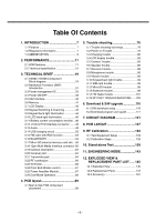
Table Of Contents 1. INTRODUCTION 7 1.1 Purpose 7 1.2 Regulatory Information 7 1.3 ABBREVIATION 9 2. PERFORMANCE 11 2.1 H/W Features 11 2.2 Technical specification 12 3. TECHNICAL BRIEF 19 3.1 KE600 / KE608 Component Block diagram 19 3.2 Baseband Processor (BBP) Introduction 21 3.3 Power management IC 33 3.4 Power ON/OFF 39 3.5 SIM interface 40 3.6 Memory 41 3.7 LCD Display 42 3.8 Keypad Switching & Scanning 43 3.9 Keypad back-light illumination 44 3.10 LCD back light illumination 46 3.11 Battery current consumption monitor ...48 3.12 JTAG & ETM interface connector ........48 3.13 Audio 49 3.14 USB charging circuit 52 3.15 FM radio with RDS function 53 3.16 BLUETOOTH 54 3.17 Micro SD external memory card slot....58 3.18 12pin Multi Media Interface connector .60 3.19 General Description 62 3.20 Receiver part 64 3.21 Transmitter part 64 3.22 RF synthesizer 66 3.23 VCTCXO 66 3.24 Front End Module control 67 3.25 Power Amplifier Module 67 3.26 Dual Mode Operation 68 4. PCB layout 69 4.1 Main & Sub PCB component placement 69 5. Trouble shooting 76 5.1 Trouble shooting test setup 76 5.2 Power on Trouble 76 5.3 Charging trouble 80 5.4 LCD display trouble 82 5.5 Camera Trouble 83 5.6 Speaker trouble 86 5.7 Receiver trouble 88 5.8 Microphone trouble 90 5.9 Vibrator trouble 92 5.10 Keypad back light trouble 94 5.11 SIM card trouble 96 5.12 MicroSD trouble 98 5.13 Bluetooth trouble 99 5.14 FM Radio trouble 101 5.13 RF PART TROUBLESHOOTING ......103 6. Download & S/W upgrade 116 6.1 S/W download setup 116 6.2 Download program user guide 117 7. CIRCUIT DIAGRAM 121 8. PCB LAYOUT 127 9. RF Calibration 133 9.1 Test Equipment Setup 133 9.2 Calibration Steps 133 10. Stand-alone Test 139 11. ENGINEERING MODE 143 12. EXPLODED VIEW & REPLACEMENT PART LIST ..... 145 12.1 Exploded View 145 12.2 Replacement Parts 147 12.3 Accessory 167 -5-

  • 1
  • 2
  • 3
  • 4
  • 5
  • 6
  • 7
  • 8
  • 9
  • 10
  • 11
  • 12
  • 13
  • 14
  • 15
  • 16
  • 17
  • 18
  • 19
  • 20
  • 21
  • 22
  • 23
  • 24
  • 25
  • 26
  • 27
  • 28
  • 29
  • 30
  • 31
  • 32
  • 33
  • 34
  • 35
  • 36
  • 37
  • 38
  • 39
  • 40
  • 41
  • 42
  • 43
  • 44
  • 45
  • 46
  • 47
  • 48
  • 49
  • 50
  • 51
  • 52
  • 53
  • 54
  • 55
  • 56
  • 57
  • 58
  • 59
  • 60
  • 61
  • 62
  • 63
  • 64
  • 65
  • 66
  • 67
  • 68
  • 69
  • 70
  • 71
  • 72
  • 73
  • 74
  • 75
  • 76
  • 77
  • 78
  • 79
  • 80
  • 81
  • 82
  • 83
  • 84
  • 85
  • 86
  • 87
  • 88
  • 89
  • 90
  • 91
  • 92
  • 93
  • 94
  • 95
  • 96
  • 97
  • 98
  • 99
  • 100
  • 101
  • 102
  • 103
  • 104
  • 105
  • 106
  • 107
  • 108
  • 109
  • 110
  • 111
  • 112
  • 113
  • 114
  • 115
  • 116
  • 117
  • 118
  • 119
  • 120
  • 121
  • 122
  • 123
  • 124
  • 125
  • 126
  • 127
  • 128
  • 129
  • 130
  • 131
  • 132
  • 133
  • 134
  • 135
  • 136
  • 137
  • 138
  • 139
  • 140
  • 141
  • 142
  • 143
  • 144
  • 145
  • 146
  • 147
  • 148
  • 149
  • 150
  • 151
  • 152
  • 153
  • 154
  • 155
  • 156
  • 157
  • 158
  • 159
  • 160
  • 161
  • 162
  • 163
  • 164
  • 165
  • 166
  • 167
  • 168

- 5 -
1. INTRODUCTION
...............................
7
1.1 Purpose
..................................................
7
1.2 Regulatory Information
............................
7
1.3 ABBREVIATION
.....................................
9
2. PERFORMANCE
.............................
11
2.1 H/W Features
.........................................
11
2.2 Technical specification
...........................
12
3. TECHNICAL BRIEF
........................
19
3.1 KE600 / KE608 Component
Block diagram
. .......................................
19
3.2 Baseband Processor (BBP)
Introduction
............................................
21
3.3 Power management IC
..........................
33
3.4 Power ON/OFF
......................................
39
3.5 SIM interface
..........................................
40
3.6 Memory
..................................................
41
3.7 LCD Display
...........................................
42
3.8 Keypad Switching & Scanning
...............
43
3.9 Keypad back-light illumination
...............
44
3.10 LCD back light illumination
...................
46
3.11 Battery current consumption monitor...48
3.12 JTAG & ETM interface connector
........
48
3.13 Audio
....................................................
49
3.14 USB charging circuit
............................
52
3.15 FM radio with RDS function
.................
53
3.16 BLUETOOTH
.......................................
54
3.17 Micro SD external memory card slot
....
58
3.18 12pin Multi Media Interface connector.60
3.19 General Description
.............................
62
3.20 Receiver part
........................................
64
3.21 Transmitter part
....................................
64
3.22 RF synthesizer
.....................................
66
3.23 VCTCXO
..............................................
66
3.24 Front End Module control
.....................
67
3.25 Power Amplifier Module
.......................
67
3.26 Dual Mode Operation
...........................
68
4. PCB layout
......................................
69
4.1 Main & Sub PCB component
placement
..............................................
69
5. Trouble shooting
............................
76
5.1 Trouble shooting test setup
....................
76
5.2 Power on Trouble
...................................
76
5.3 Charging trouble
....................................
80
5.4 LCD display trouble
................................
82
5.5 Camera Trouble
.....................................
83
5.6 Speaker trouble
......................................
86
5.7 Receiver trouble
.....................................
88
5.8 Microphone trouble
................................
90
5.9 Vibrator trouble
......................................
92
5.10 Keypad back light trouble
.....................
94
5.11 SIM card trouble
...................................
96
5.12 MicroSD trouble
...................................
98
5.13 Bluetooth trouble
..................................
99
5.14 FM Radio trouble
...............................
101
5.13 RF PART TROUBLESHOOTING
......
103
6. Download & S/W upgrade
...............
116
6.1 S/W download setup
............................
116
6.2 Download program user guide
.............
117
7. CIRCUIT DIAGRAM
......................
121
8. PCB LAYOUT
................................
127
9. RF Calibration
..............................
133
9.1 Test Equipment Setup
.........................
133
9.2 Calibration Steps
..................................
133
10. Stand-alone Test
........................
139
11. ENGINEERING MODE
................
143
12. EXPLODED VIEW &
REPLACEMENT PART LIST
.....
145
12.1 Exploded View
..................................
145
12.2 Replacement Parts
............................
147
12.3 Accessory
.........................................
167
Table Of Contents