LG KE600 Service Manual - Page 52
FM radio with RDS function
 |
View all LG KE600 manuals
Add to My Manuals
Save this manual to your list of manuals |
Page 52 highlights
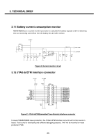
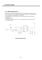
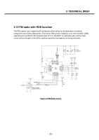
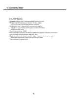
3. TECHNICAL BRIEF 3.15 FM radio with RDS function The FM receiver uses a digital low-IF architecture which allows for the elimination of external components and factory adjustments. The receive (RX) section integrates a low noise amplifier (LNA) supporting the worldwide FM broadcast band (87.5 to 108 MHz). An automatic gain control (AGC) circuit controls the gain of the LNA to optimize sensitivity and rejection of strong interferers. FM_INTn TP310 C326 24p L303 100nH C368 NA D308 PG05DBTFC 2V85_IO2 VBAT TP311 TP312 100p C332 R328 0 R329 NA 25 PGND 24 GND6 23 NC2 NC1 22 GPIO1 21 GPIO2 20 GPIO3 19 2V72_IO 1 2 GND1 3 FMIP 4 RF_GND 5 6 FMIN GND2 GND3 U303 SI4701 18 VA 17 GND5 16 LOUT 15 ROUT GND4 VD 14 13 7 8 _RST _SEN 9 SCLK 10 SDIO 11 RCLK 12 VIO CLK32K 2V72_IO R336 10K U305 VCC A Y FM_RESETn SCL SDA C338 0.1u GND MC74VHC1GT50DFT2 -> MC74VHC1GT50DF1G R337 0 2V72_IO C337 220n FM_L FM_R C335 4.7u C336 22n Figure 27 FM Radio circuit - 53 -
-
 1
1 -
2
-
3
-
4
-
5
-
6
-
7
-
8
-
9
-
10
-
11
-
12
-
13
-
14
-
15
-
16
-
17
-
18
-
19
-
20
-
21
-
22
-
23
-
24
-
25
-
26
-
27
-
28
-
29
-
30
-
31
-
32
-
33
-
34
-
35
-
36
-
37
-
38
-
39
-
40
-
41
-
42
-
43
-
44
-
45
-
46
-
 47
47 -
 48
48 -
 49
49 -
 50
50 -
 51
51 -
 52
52 -
 53
53 -
 54
54 -
 55
55 -
 56
56 -
 57
57 -
58
-
59
-
60
-
61
-
62
-
63
-
64
-
65
-
66
-
67
-
68
-
69
-
70
-
71
-
72
-
73
-
74
-
75
-
76
-
77
-
78
-
79
-
80
-
81
-
82
-
83
-
84
-
85
-
86
-
87
-
88
-
89
-
90
-
91
-
92
-
93
-
94
-
95
-
96
-
97
-
98
-
99
-
100
-
101
-
102
-
103
-
104
-
105
-
106
-
107
-
108
-
109
-
110
-
111
-
112
-
113
-
114
-
115
-
116
-
117
-
118
-
119
-
120
-
121
-
122
-
123
-
124
-
125
-
126
-
127
-
128
-
129
-
130
-
131
-
132
-
133
-
134
-
135
-
136
-
137
-
138
-
139
-
140
-
141
-
142
-
143
-
144
-
145
-
146
-
147
-
148
-
149
-
150
-
151
-
152
-
153
-
154
-
155
-
156
-
157
-
158
-
159
-
160
-
161
-
162
-
163
-
164
-
165
-
166
-
167
-
168
 |
 |
